The management interface is located above the console port on the rear panel of the Mobility Access Switch. It is labeled as mgmt. The management port is a dedicated interface for out-of-band management purpose. When connecting a PC to the Ethernet management port, you must first assign an IP address. Whereas, a Console Port is a serial interface used for direct, local device access via a console cable, typically during initial setup or troubleshooting. This interface is specifically available for the management of the system and cannot be. Right now, it won't, because no device points to the switch's Mgmt. IP as a gateway, but all one would need to do is connect to a port on the Mgmt. VLAN and manually enter the switch IP as a gateway and then you'd be able to route between all four subnets. The solution is to remove the VLAN. You can access and manage the switch using the GUI (Graphical User Interface, also called web interface in this text) or using the CLI (Command Line Interface). There are equivalent functions in the web interface and the command line interface, while web configuration is easier and more visual than. This topic describes how to configure the management port. It includes the following information: You connect the management port to an Ethernet switch or router that is part of your internal local area network (LAN) and that can connect to your network management infrastructure.
[PDF]

This video goes over common types of connectors, their respective adapters, and how to properly connect and disconnect them. more Are you interested in seeing how fiber optic connectors get. Unplugging a fiber jack, also known as a fiber optic connector, is a delicate process that requires attention to detail and proper handling to ensure the integrity of the fiber optic cables and connectors. Fiber optics are used in a variety of applications, including telecommunications, internet. If you're wondering how to remove fiber optic cable from connectors, there are a few different ways to do it. You need to know which connector is the correct one for the cable and what kind of wire it's made of. You can also use shears or wire cutters to cut through the connector. This article. Fiber optic connectors are essential components in fiber optic networks, providing a reliable connection between cables and equipment. Removing these connectors requires care to avoid damaging the delicate fibers or the connector itself. To connect a fiber optic cable to SFP optical module, first ensure the SFP is fully inserted into the network port until it "clicks", then remove the dust caps from both the SFP and the LC fiber optic connector.
[PDF]
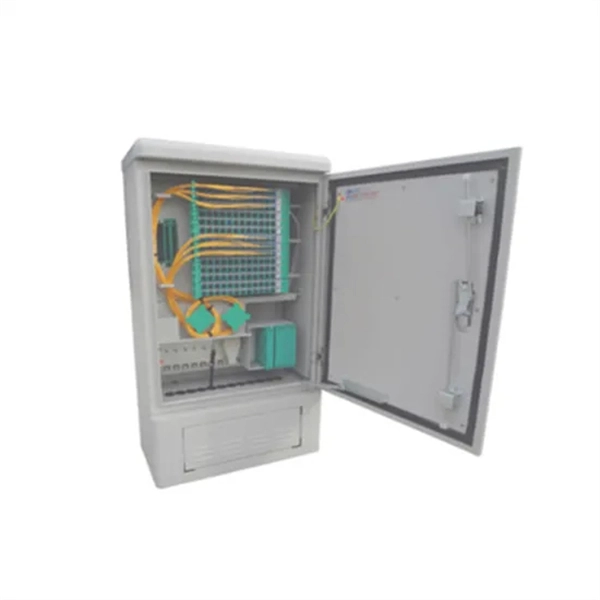
They function as junction points that manage, protect, terminate, and distribute fiber optic cables, ensuring efficient data transmission between different network elements. Fiber Distribution Boxes (FDBs) are critical components in modern telecommunications infrastructure, particularly in fiber optic networks. Whether you're a network technician, IT professional, or simply looking to understand fiber optic networks. A fiber distribution box (FDB) is a passive enclosure that provides secure splicing, termination, and distribution of optical fibers. It typically contains splice trays, adapters, and cable routing components to manage fiber connections. FDBs are used to organize incoming and outgoing cables. Discover Fiber Distribution Hubs (FDHs), fiber cabinets, and other outdoor cabinet solutions by CommScope. Efficiently manage your network with our reliable fiber optic distribution cabinet solutions.
[PDF]

The SS64S16A (L-16. 2,SC) is a Huawei high-performance STM-16 optical interface board designed to deliver 2. 5 Gbps long-haul transmission across SDH transport networks. The SFP-FE-SX-MM1310 (part number: 02315233) is a Huawei-certified 100M optical module. However, the Vendor Name field displays the original manufacturer name, instead of HUAWEI. Huawei. Optical modules are widely used in switches, network interface cards (NICs), routers, and other communication devices. During use, reading optical module information helps understand its real-time operating status, enabling faster troubleshooting of link abnormalities. The following uses the. Original SFP Huawei GPON-OLT-CLASS-C+/C++ Optical Module GPON Optical Module A GPON optical module is connected to one SC optical fiber to provide GPON access service. Return Material Authorization (RMA) Process Standard Hardware Warranty Policy: Original new sealed ZTE product: 1 Year The Support. Problem: All optical ports cannot be connected, and the indicator lights are not on. Solution: To solve this problem, you can follow these steps: Check if the fiber and optical modules are compatible. Perform a. Huawei GPON boards include GPON, XG-PON, XGS-PON, XG-PON&GPON Combo, XGS-PON&GPON Combo interface board, so there are these kinds of GPON optical modules corresponding. The following figure shows the optical modules supported by the S5720-12TP-LI-AC. You can also use the Hardware Center to query the.
[PDF]

No, a 10G SFP (Small Form-factor Pluggable) module is designed to operate at 10 Gigabits per second (Gbps) and is not compatible with a 1 Gigabit per second (Gb) port. Therefore, a 10G SFP module will not work. When SFP optical module is inserted into the SFP port of Gigabit switch with fiber optic patch cable or copper cable, it can realize different distance transmission. For example, the maximum transmission distance is 160 km when using SFP1G-ZXC-55 optical module and LC duplex fiber patch cable, and. 10 Gigabit Ethernet (10GE, 10GbE, or 10 GigE) is a group of computer networking technologies for transmitting Ethernet frames at a rate of 10 gigabits per second. It was first defined by the IEEE 802. For example, when using the AE-SFP-ZX160 optical module and LC duplex fiber optic patch cords, the maximum transmission. Can 1G SFP optics work with 10Gb SFP+ ports on a 10Gb switch, or vice versa? This comprehensive guide reveals the intricacies of SFP and SFP+ compatibility and provides useful solutions for network switch users. Can 1G SFP Optics Run at 10G SFP+ Port? Can 10G SFP+ Optics Run at 1G SFP Port? Can. Small form-factor pluggable or SFP Modules can be described as compact and hot-pluggable hardware that connects various networking devices such as servers, routers, and switches. Networking standards, including Ethernet, Fiber Channel, and SONET, are also used with the SFP modules, broadening their.
[PDF]
The ProCurve Switch 2800 series consists of two switches: the 24-port ProCurve Switch 2824 with 20 10/100/1000 ports, and the 48-port ProCurve Switch 2848 with 44 10/100/1000 ports. In addition, each switch has 4 dual-personality ports for RJ-45 10/100/1000 or mini-GBIC fiber. Manuals and User Guides for HP ProCurve 2848. We have 3 HP ProCurve 2848 manuals available for free PDF download: Function Manual, Install Manual, Datasheet Hp ProCurve 2848 Pdf User Manuals. View online or download Hp ProCurve 2848 Function Manual, Install Manual, Datasheet. I am going to link the following 3 switches, HP Aruba 2920-48 POE, 2510-48 and 2848, by double fibre optic cables (through the miniGBIC slots) so double link from the 2920 to the 2510 and the a double link to the 2848. You can examine HP ProCurve 2848 Manuals and User Guides in PDF.
[PDF]
The transceiver is available as a mini-GBIC form factor, making it ideal for environments that require many fiber connections by taking up less space in your cabinet and/or computer room. Compatibility in your network is everything, and the Intellinet SFP Transceiver Module delivers. Use it with any Intellinet SFP equipped network switch or any other MSA-compliant, SFP-enabled switch. And since the Intellinet SFP transceiver module is set to broadcast the vendor on GLC-LH-SM, compatibility to your Cisco gear is provided. No need to power down your LAN switch in order to install or remove the transceiver. This makes it very convenient and easy for you to make adjustments to your network that allow your business to keep pace with the changing demands of the market.
[PDF]

DANGER Never look directly into an optical module or the ends of optical fibers. Optical modules and connected fibers emit laser radiation that can cause eye damage. NOTICE ● A switch must use optical or copper modules that have been certified for use on. Description: Huawei switches must use Huawei-certified optical modules. Non-Huawei-certified optical modules cannot ensure transmission reliability and may affect service stability. Huawei is not responsible for any problem caused by the use of non-Huawei-certified optical modules and will not fix. How to Configure Optical Ports on Huawei S5720-32P-EI-AC Switch? Problem: All optical ports cannot be connected, and the indicator lights are not on. Solution: To solve this problem, you can follow these steps: Check if the fiber and optical modules are compatible. Single-mode/multimode fibers and. Install an optical module on a port before connecting optical fibers to the transceiver module. Install dust plugs on idle optical ports. Wear an ESD wrist strap or ESD gloves. Before connecting the optical fiber to the. The method used to install a copper transceiver module is the same, except that the copper transceiver module connects to a network cable instead of optical fibers.
[PDF]
According to different types of pigtail cable connector terminated at the end, there are LC fiber pigtail, SC pigtail, ST pigtail, FC pigtail, fiber pigtail and so on. With different structures and appearance, each of them has their own advantages in diffe. According to different types of pigtail cable connector terminated at the end, there are LC fiber pigtail, SC pigtail, ST pigtail, FC pigtail, fiber pigtail and so on. With different structures and appearance, each of them has their own advantages in different applications and systems. Let's go through some widely used ones. SC Pigtail: SC pigtail. Fiber Optic Pigtails, In fiber optic cable installation, how cables are attached to the system is vital to the success of network. If done properly, optical signals would pass through the link with low attenuation and little return loss. pigtail offers an optimal way to joint optical fiber, which is used in 99% of single-mode applications. This pos. pigtails can be divided into single-mode (colored yellow) and multimode (colored orange) fiber. Multimode pigtails use 62.5/125 micron or 50/125 micron bulk multimode fiber cables and terminated them with multimode fiber optic connectors at one end. 10G multimode fiber cables (OM3 or OM4) are also available in optic pigtails. The jacket color of 10.
[PDF]
You can access the switch through the serial console port or the Mini USB console port. Only the Mini USB console port is available if you connect both the serial console port and Mini USB console port. This chapter describes how to connect your switch to a network. In this video tutorial I show you How to configure Access Port in H3C switch, how to configure Trunk Port in H3C switch, How to All. more Hello Friends, In this video I will show you H3C Switch Configuration. On the switch, you can configure Telnet or SSH for remote access through Ethernet ports.
[PDF]

One SFP module is inserted into the switch's SFP port, and another module is inserted into the SFP port of the target device, facilitating data transmission through the fiber optic cable. SFP ports are small hot-pluggable module interfaces typically used for connecting fiber optics or copper cables. They support various transmission rates and distances, including 1G, 10G, and higher speeds. SFP modules can be selected based on the requirements, whether it's single-mode fiber for. An SFP port is a physically small slot in a networking device that accepts an SFP module insert. Most modern networking devices, such as Ethernet switches, servers, routers, network interface cards, and fiber media converters, generally have two or more built-in SFP ports. You may connect different. In plain terms, an SFP port on a gigabit switch is the little plug-in hole that gives the switch physical flexibility — the ability to use fiber one minute and copper the next without buying a different switch. Unlike fixed RJ45 copper ports, SFP ports support both fiber and copper modules, enabling far longer distances, greater flexibility, and improved scalability in enterprise. First, to connect SFP modules with fiber optic cables, ensure that the module type matches the line, as there are different modules for single-mode and multimode fiber. Next, insert the module firmly and securely into the SFP port, then attach the cable to the module using the connector. Switches with SFP ports can.
[PDF]

Compare all 12 PoE switches we tested with their key specifications, power budgets, and ideal use cases. This comprehensive overview helps you quickly identify which model matches your specific requirements. We earn from qualifying purchases, at no additional cost to you. The Aruba Instant On 1930 24-Port is the best PoE switch for most small to medium businesses because it delivers enterprise-grade features with cloud-based management at one-third the cost of Cisco alternatives. After testing 12 switches for 45 days with various real-world scenarios including 16 IP. Me gustaría estar al día con las noticias, actualizaciones de productos y promociones de TP-Link. Al completar este formulario, confirma que comprende y acepta nuestra Política de privacidad. After testing 27 different models over 14 months in various real-world scenarios—from small home offices to enterprise deployments—the TP-Link TL-SG1005P stands out as the best PoE switch for most users due to its perfect balance of simplicity, reliability, and affordability. Our testing involved.
[PDF]
Being managed or unmanaged in a Power over Ethernet switch is the part that defines whether or not you want to take control of your PoE switch and be responsible for everything that occurs in your net.
[PDF]