
This blog article entry considers the merits of choosing which of various low loss RF coaxial cables to use for IoT, LTE or LORA wireless applications where an external antenna is used to connect to router, gateway or terminal. The choice looks deceptively simple—pick a length, screw it on—but RF engineers know the truth: every extra meter quietly eats away at your link budget, especially once you cross 2 GHz. It's not just about length; the cable type, connector quality, and even mounting environment make a measurable. Audio generated by DropInBlog's Blog Voice AI™ may have slight pronunciation nuances. In this article, we will consider cables such as RG174, RG58, RF195. The cheap connectors have inferior dielectric between the poles as well as poorer grades of metal. The dielectric won't handle high power (KW range) as well and the center pin can more easily shift causing impedance problems if they are moved frequently. RF connectors are usually used with coaxial cables. They are designed to maintain the shielding that the coaxial design offers. The better and newer. Besides the wide range of RF connectors, Telegärtner also provides a considerable range of suitable coaxial low loss cables. Using this one-stop shopping option at Telegärtner makes your purchasing process even more efficient. The main use of low loss cables are all kinds of wireless applications.
[PDF]

Compare fiber optic and copper Ethernet cables across speed, distance, cost, installation difficulty, and use case metrics. Use the interactive scenario selector to find the right medium for your specific network — all processed locally in your browser. PoE Required?. The core difference between fiber optic and copper cables lies in how they carry data. One uses light, the other electricity—and that distinction shapes everything from speed to signal integrity. Fiber optics transmit data as pulses of light through ultra-thin strands of glass or silica. Both technologies can deliver high-speed connectivity, but they behave differently under real-world constraints such as. However, the exponential growth in data demand has positioned fiber optic technology as the superior alternative for performance, scalability, and future-readiness. This article provides a detailed technical comparison between fiber optic and copper cables, offering a clear perspective for. Fiber optic tends to be the more premium solution, while copper wiring is far more common, but why is that? What are the differences between these two cable types, and why might you want to pick one over the other? Here's everything you need to know about fiber vs. copper cables, to help you pick. Several factors are converging to drive the switch from copper to fiber – and cost is a big one. A recent investor presentation by AT&T claimed that fiber was 35% less costly to maintain than copper.
[PDF]

This article provides a detailed technical comparison between fiber optic and copper cables, offering a clear perspective for engineers, network architects, and procurement managers. The core distinction between the two technologies lies in the physics of data. However, the exponential growth in data demand has positioned fiber optic technology as the superior alternative for performance, scalability, and future-readiness., 10G/25G/40G/100G and beyond depending on optics and reach). Copper Ethernet scales too, but practical limits are lower and depend. The two main options are fiber optic cables and copper cables, each with its own advantages and drawbacks. Fiber optic cables are praised for their high performance and scalability, while copper cables remain a cost-effective choice, especially for budget-conscious projects and older systems. Copper wire is more susceptible to interference and has limited data capacity, making optical fiber the preferred choice for modern high-speed. Optical connectivity, utilizing fiber-optic technology, has emerged as the superior choice for modern networking, offering unparalleled performance, reliability, and scalability. For example, a typical 10 Gbps copper Ethernet link (such as Cat 6A) over 100 meters can consume approximately 5 to 8+.
[PDF]

Insertion loss tells you how much weaker the signal becomes after passing through the splitter. Let's say you have a laser output at 0 dBm (which is 1 milliwatt of optical power). If you use a 1×8 splitter with ~10. 5 dB of insertion loss, the power at each output would be: 0 dBm – 10. 5. Enter excess loss from the splitter datasheet for your wavelength. Add connector and splice quantities with realistic planning losses. Include any additional component losses and an engineering margin. Enable power budget to estimate received power and margin. Press Calculate to show results above. Understanding optical splitter loss isn't just about plugging numbers into a calculator. It's about knowing what factors contribute to that loss, how manufacturers specify it, and how it impacts the overall performance and reach of your network. Ignore it, and you might find your signal too weak to. Optical insertion loss refers to the signal loss resulting from the insertion of components such as connectors or splices in an optical fiber system. Common ratios: For cascades, add losses and validate margin using the Optical Budget tool. This Fiber Optic Splitter Insertion Loss is the splitter devices loss, Considering fiber connectors or connectors+adapter insertion loss in LGX, The fiber splitter IL would be a little bigger. To make clear the basic ftth fiber splitter loss in performance, You can refer to the below loss chart.
[PDF]

The primary problem encountered is signal loss, also known as attenuation. Attenuation can be due to absorption, scattering, or bending losses, affecting the quality and speed of data transmission. Attenuation in fiber optic cables is the reduction in signal strength during. To be able to judge whether a fiber optic cable plant is good, one does a insertion loss test with a light source and power meter and compares that to an estimate of what is a reasonable loss for that cable plant. The estimate, called a "loss budget" is calculated using typical component losses for. F iber optic networks rely on the efficient transmission of light signals to deliver high-speed data over long distances. However, various factors can cause signal degradation, leading to performance issues and reduced network reliability. Fiber optic signal loss, also known as attenuation, occurs. A significant signal loss in the optical fiber can cause unreliable transmission. How can we know the value of losses on the fiber link? Read on, this post will teach you how to calculate the losses in optical fiber and judge the fiber link performance. The uses various types of network cables, including multimode and single-mode fiber-optic cable. It can also break your connection. High attenuation makes your system not work well. You should fix it fast to get speed and stability back. > You can solve this with simple steps.
[PDF]

d Lighting Co Plc, here known as Kenya Power. This specification lays down requirements for Low Voltage (LV) Enclosures and Accessories for use in Advanced Metering Infrastructure (AMI) system. d Lighting Co Plc, here known as Kenya Power. Secpower Technologies LTD specializes in. Browse our comprehensive range of electrical products — from switchgear and panels to VFDs and smart components. ATS/MTS solutions from Paneltech Systems provide reliable Automatic and Manual Transfer Switches for seamless power transfer in industrial and commercial electrical systems. Distribution. th cable entry and termination of cables. Secure and Intelligent Spaces, Powered by HSC ELV Systems We deliver holistic Extra-Low Voltage (ELV) solutions that integrate Security, Fire and Automation into intelligent ecosystems. More than just equipment, our systems provide seamless control, uncompromising safety and optimised performance. Are you searching for a reliable Low Voltage (LV) Power Control Panel manufacturer in Kenya? We are Kenya's trusted source for custom-designed and precision-engineered power panels built for long-term performance and safety in industrial, commercial, and institutional setups. 🏭 Who We Are We are a.
[PDF]

240V/415V 3-phase power; 20 or 30 Amp power input feed option. Precisely measure the aggregate current draw (in amps) on each phase. On-site veri cation of the input current with the LED digital display. This manual contains important safety instructions that should be followed during the installation and maintenance of the VertivTM SmartCabinetTM. Read this manual thoroughly before installing or operating this unit. Any. Page 1 SmartCabinet™ User Manual. Page 2 Customer Service Hotline: 4008876510 India Email: customer. com. The DeltaV SISTM Configure-To-Order (CTO) CHARMs Smart Logic Solver (CSLS) Cabinets provide an off-the-shelf solution for faster project execution and reduced installation costs. CTO CSLS Cabinets are factory tested and ready for installation in technical rooms. Electronic Marshalling eliminates. Please click download button for getting Brochure Please click download button for getting Image For More Information about product please contact us. We help strengthen the world's most vital applications by bringing together global reach and local knowledge, and our decades-long heritage, including brands like Chloride, Liebert, NetSure, and Trellis. With a unique combination of industry expertise, technology, and resources, our mission is to. The Smart BDFB is a high capacity secondary distribution system which combines Alpha's successful BDFB platform with the capability to monitor and alarm system parameters via IP/ SNMP capabilities.
[PDF]
Voltage Limits: Set upper/lower bounds to match your grid requirements. MPPT Tracking: Adjust Maximum Power Point Tracking for varying sunlight conditions. Frequency Response: Ensure synchronization with grid frequency (50Hz or 60Hz). This paper presents a concise discussion and an investigation of the most literature-reported methods for modifying the lumped-circuit parameters of the single-diode model (SDM) of a photovoltaic (PV) module, to suit the prevailing climatic conditions of irradiance and temperature. These. This page gives access to several tools for the determination of all secondary parameters of the PV module model. PVsyst always proposes default values which may be recovered by clicking the " Default " checkboxes. The main goal is to determine the optimal parameter. This guide will walk you through practical steps to optimize your inverter settings, whether you're a solar technician, project manager, or a business owner looking to maximize ROI. Think of your inverter as a translator between solar panels and the grid. If it's not “speaking the right language,”.
[PDF]
The product structure mainly consists of cover, housing, explosion-proof latch, built-in circuit breaker or explosion-proof circuit breaker, and terminal blocks. The component cavity is flameproof, the wall thickness is up to 12mm, and the inlet cavity is increased in. Flameproof enclosure (Ex d IIB+H2), which can be used as feed distribution equipment in control and distribution system (such as distribution box, switch box of main circuit, control box, terminal box or motor starting box etc. ) ·Enclosure: stainless steel. Equipped with specialized hinge. Explosion-proof lighting distribution boxes and cabinets come in a variety of models. They vary in terms of materials, including metal and flame-retardant plastic; installation methods, such as vertical, hanging, concealed, or exposed installations; and voltage levels, including 380V and 220V. It is also used in flammable dust places such as military industry, port, grain storage and metal processing; 2. Ideal for marine platforms, chemical tankers, LNG vessels, and dangerous cargo wharfs, these robust distribution boxes ensure reliable. Explosion proof junction boxes with detachable covers which are secured to the body by high tensile screws. Available in five sizes, these boxes provide a wide range of termination and distribution facilities. Integrally cast plates are provided for different combinations of cable entries on any of.
[PDF]

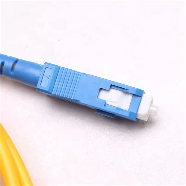
IEC fiber connector standards establish the global specifications for connector geometry, mating interfaces, optical performance classes, and mechanical testing across all fiber network environments. Optical connectors are used to connect optical devices to other optical devices or systems. However, each connection introduces a certain amount of insertion and return loss that. Connectors play an important role in Enterprise network architecture. They give you the power to add, drop, move, and change the network. is a small cylinder used to mount. The Fischer FiberOptic Series offers robust and faultless optical performances in any conditions. Combined with easy use, cleaning and maintenance. Tested for harsh and extreme environments (Norm IEC 61753-1 Cat. These standards ensure that passive fiber-optic components remain interoperable, stable, and. designed for diverse fiber optic applications. But what exactly sets a fibe optic connector apart in terms of its merits? The primary purpose of a fiber optic connector is to terminate the ends of fiber optic cables, ensuring they can be int rconnected reliably with minimal optical loss. After. Fiber optic technology is used in ever-increasing applications due to its inherent advantages (lower weight, EMI/RFI immunity, higher bandwidths and distances) over copper. There are many.
[PDF]

In this paper, various operational factors affecting 100G transmission over G. D fiber-cables are discussed to make the right fiber selection for the long-haul network. Selecting appropriate G. 652 fibre was originally optimized for use in the 1310 nm wavelength region but can also be used in the 1550 nm region. This is the latest revision of a Recommendation that was first created in 1984 and deals with some relatively minor modifications. a number of concatenated cable. G. 92% of. Fiber optic cables are the ultimate technology used in data transfer using light waves. They are classified based on wavelength band, core/cladding size, application, and compliance with international standards such as IEC, ITU-T, and TIE/EIA. In the next sections, the real artwork is putting on. This guide explains the most important ITU-T G. 655—to help you make an informed decision for your project, whether it's a long-haul backbone or a final FTTH drop. In the world of fiber optics, not all glass is created equal. The core of every cable—the optical. Because GPON and XGS-PON are deployed in diverse environments, fiber-containing components such as PLC splitters must be evaluated not only by their standard parameters but also by their sensitivity to bending loss, which is critical for maintaining stable optical transmission. The ITU-T defines.
[PDF]

Optical splitters play a crucial role in Fiber to the Home (FTTH) Passive Optical Network (PON) systems, efficiently distributing a single optical signal to multiple destinations. The split ratio and insertion loss are two key parameters defining their performance. Understanding Fiber Optic Splitters: Principles, Parameters, Types, Applications, and Future Trends 1. Introduction Fiber optic splitters are integral components in the world of optical networks. A deeper understanding of these. 📄 What is an Optical Splitter? An Optical Splitter, also known as a beam splitter, is a passive optical device that divides a single input optical signal into two or more output signals. Conversely, it can also combine multiple signals into one. Its primary role is in Passive Optical Networks. Bandwidth is shared amongst customers in a PON, and the bandwidth received by a customer is not related to the power received at the optical network terminal (ONT) as long as the power is high enough so the ONT can operate. Their ability to efficiently manage optical signals makes them indispensable in various. The performance of optical beam splitters can significantly influence the overall performance of laser-based instrumentation and measurement systems. This paper examines two of the most critical performance factors: optical efficiency and wavefront distortion. Efficiency is a function of both the.
[PDF]

This paper is focused on the performance analysis of protection mechanisms utilized in common wavelength division multiplexing-based passive optical networks. Wavelength division multiplexers are fundamental to the functioning and performance of integrated photonic circuits, with applications ranging from optical interconnects to sensing and quantum technologies. Current solutions are limited by trade-offs between channel spacing, crosstalk, insertion. Wavelength division multiplexing (WDM) is a technology for increasing the transmission capacity of optical fiber communications by sending multiple data channels simultaneously through a single fiber, each on a different wavelength of light. The main aim of the proposed research is providing an option of comparing different traffic protection scenarios for advanced optical. Herein, an attention-grabbing and up-to-date review related to major multiplexing techniques is presented which includes wavelength division multiplexing (WDM), polarization division multiplexing (PDM), space division multiplexing (SDM), mode division multiplexing (MDM) and orbital angular momentum. The journey of optical multiplexing began in the 1970s with the introduction of Wavelength Division Multiplexing (WDM), which revolutionized the capacity of optical communication systems. The primary objective of optical multiplexing has been to maximize the utilization of available bandwidth in.
[PDF]