
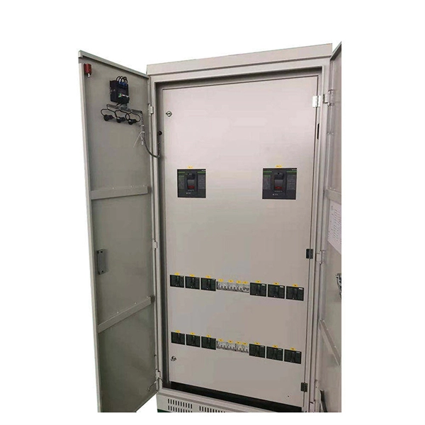
Connect the phase and neutral wires from the input power supply to the input of the Main MCB. Learn how to install a distribution box safely and correctly. Covers wiring, placement, standards, and expert tips for a compliant setup. It takes the incoming power and safely distributes it to different circuits throughout your building. Learn how to wire a distribution box step by step! This video shows real on-site footage of electrical installation, demonstrating safe and standardized wiring methods used by professionals. Below is a quick checklist of everything you will need for a safe and efficient installation: Connecting a distribution box involves several steps to ensure proper electrical flow. It is usually equipped with circuit breakers, fuses, terminal connectors, and other components. It is mainly used to isolate fault circuits, prevent overload, and ensure the safe operation of. Box installation: Make sure that Distribution box has been correctly installed and fixed. Location determination:. An electrical panel box, also known as a breaker box or a distribution board, is a crucial component of any electrical system. It serves as a central hub for distributing electricity throughout a building, ensuring that power is delivered safely and efficiently to all the required locations.
[PDF]

Step-by-step guidance on installing an electric meter box safely—site prep, clearances, mounting height, wiring, grounding, permits, and code compliance explained. Learn safety tips, wiring steps, troubleshooting, and when to call a pro. An electric meter box measures how much electricity your home uses. It helps the utility company give you the right bill. If you're setting up a new one or replacing an. It is a box that is hard to access, fails inspection, or cannot support future loads and upgrades. Then I fix the box securely, route and terminate cables neatly, seal. An electric meter box looks simple from the outside. It is just a box on a wall. But the way it is installed affects safety, compliance, maintenance, and even how fast you can get utility approval. A sloppy installation can create small problems that stay hidden for years. Installing an electric meter box might seem like a job for professionals only—but with the right knowledge, it's a task many homeowners. In this guide, we will break down the key elements involved in connecting the main power supply to your home, providing a clear path for a successful setup. We will focus on the critical parts of the system, from basic components to step-by-step assembly procedures. The Owner/Contractor is required to fix instal electric transmission or distribution system. OUC may remove any such equipment installed between the transformer to the meter and may require the Customer, as.
[PDF]

This guide covers the critical steps, from selecting the right electrical cable tray and performing accurate cable fill calculations to managing a safe cable pull through and ensuring all bonding and grounding requirements are met. Article Summary: A compliant cable tray installation requires a thorough understanding of NEC Article 392, proper structural support, and precise installation techniques. Structural building members should never be cut, and cable trays should not be installed in hoist ways or where subject to physical damage. Cable tray systems re to be installed so that they are accessible. Here is a step-by-step guide on how to install a standard metal cable tray system (e., ladder or perforated type). But before you lay the first tray or clamp down a single cable, you need a solid plan. When ofloading tray from a flat deck trailer using an overhead crane, care should be exercised in the placement and length of the slings to prevent crushing the product (siderails). Only ofload. Cable tray systems are designed for easy installation and to accommodate power, communications, and signal cabling across a variety of applications. When properly installed, cable trays prevent damage to cabling and the area's structural integrity. When installed and engineered properly, cable.
[PDF]

The cost to install fiber optic cable ranges from $1. 50 to $42 per foot, with installation costs accounting for 60-80% of total project expenses. According to the Fiber Broadband Association's 2025 report, median costs are $8 per foot for aerial builds and $18 per foot for. Fiber optic cable installation costs between $1,500 and $7,000 for your home, with prices varying by cable length and installation method. The installation type you choose and the layout of your property determine the total labor and materials needed for your project. You should account for permit. The initial cost of installing fiber optic cables can vary depending on the chosen installation method and specific project requirements. Total Project Costs: For commercial installations, expect costs ranging from $5,000 to $20,000 per mile for underground projects and from $40,000 to $60,000 per. Homeowners and businesses typically pay for fiber optic cable installation based on distance, conduit needs, and labor. The main cost drivers include material type, run length, trenching or aerial work, and any required permits or inspections. This comprehensive guide breaks down the factors influencing pricing, average expenses, and tips to get the best value in 2025. Clear insights help make informed decisions without unexpected surprises. Let's start by getting a better idea about the material cost. Understanding the fiber cable cost per foot is crucial before.
[PDF]

Price and other details may vary based on product size and color. Enclosed AC/DC Power Relay with Protection & De-Bounce. Need help?. Detect and mitigate ground faults to prevent harm to equipment, circuits, and people. These relays monitor the differential between incoming and outgoing current, also known as residual current. When the balance is off, they trip and cut power to the circuit. These relays are highly sensitive, so. Protect high-impedance grounded generators from ground faults at standstill, during startup, and while running by using the multisine frequency injection and neutral overvoltage-based protection in the SEL-2664S Stator Ground Protection Relay. Littelfuse produces relays for grounded and ungrounded systems. When conditions for a ground fault exist. Protection relays detect abnormal operating conditions in an industrial system and may trigger an alert or isolate the offending device from the system. Common detection functions include; Arc-flash, temperature monitoring, ground fault, over-current, over-voltage, reverse power flow. Model GFP, Ground Fault Relay, Door Mount, 120VAC, without Interlock, 100-1200 Amp Trip Current, Electromagnetic Industries GROUND FAULT CURRENT DETECTION The GFP system is designed for electrical equipment protection, not for personnel protection Application: These Class 1 (Model GFP) Ground Fault.
[PDF]

It's called a breaker box, and even though it might not look very exciting on the outside, what's behind that little door is the heart of your home's electrical system. Bottom Line Up Front: Your home's distribution box (electrical panel) is typically located in the basement, garage, utility room, or mounted outside near your electrical meter. To find it quickly, look for a rectangular gray metal box about the size of a medicine cabinet, often positioned close to. Electrical panel boxes, aka breaker boxes, can be on a wall in an out-of-the-way area of your home. You can find electric panels inside cabinets, behind refrigerators, or inside clothes closets in older homes. Current National Electrical Codes (NEC) allow none of these locations. Electrical panels. The electrical panel is the central hub that distributes electricity throughout the house. Knowing where to find your electrical panel in your home helps in case of emergencies and routine maintenance. Panels are commonly found in garages, basements, utility rooms, and outdoor walls. Understanding how your electrical panel works can help you troubleshoot issues, perform basic maintenance, and know when to. When something electrical goes wrong in your home—like a tripped circuit or sudden power outage in one part of the house—most people instinctively head to that gray metal panel, often hidden in a basement, utility closet, or garage. Having the breaker box.
[PDF]

Relay burnout may have been caused by overcurrent, overvoltage, vibration, or short circuit. (It does not mean that the relays burn continuously with flames, because flame-retardant materials are used for the relay components. ) Contact vibration (ultra-frequent switching) causes continuous arcing. Relays burn out for several reasons. Overcurrent is a common cause, where too much current flows through the relay, generating excessive heat. Overvoltage can also damage the relay by applying a voltage higher than it can handle. It requires replacement, but the root cause of the burn-out needs to be identified and resolved first. We mainly use them as they can be used to control much larger levels of power by only using a small level of input power. They also act as an electrical isolation devices as they separate the power circuitry from the. There are several reasons why a relay may fail, including: Excessive current or voltage: A relay may fail if it is exposed to excessive current or voltage, which can burn out the contacts or damage the coil. Mechanical wear and tear: Relays that are used frequently can experience mechanical wear. Relays are basically switches that take up a small control current and use it to administer higher voltage loads. There are varieties of relays and they include General Purpose Relays, Power Relays, Miniature Relays, and PCB Power Relays. In this blog, we review typical failures witnessed with.
[PDF]

This article provides a comprehensive guide on installing fiber optic patch panels, integrating practical installation steps with insights from business intelligence and data analytics. How to Install Fiber Optic Patch Panel Only by taking the proper steps can achieve a reliable network. For your convenience, the patch panel installation guide is divided into two sections. A successful project begins with careful planning. Whether you are a seasoned professional or new to the field, this guide is designed to enhance your understanding. ⚡ Level Up Your Fiber Skills – Join the One Up Techs Skool 👉 https://www. com/oneuptechs Please like, Subscribe, and comment any questions you may have. com/oneuptechs Most techs struggle because they: ❌ Don't. Keeping this page as a placeholder for now. What are the best practices for fiber patch panel installation? The best practices below help to avoid installation issues and ensure ease of service for the system. Penetrate the enclosure from the side or bottom to minimize the risk of water intrusion. Install grommets on all openings before. The fiber optical patch panel is convenient for people to easily access the optical fiber cable in the panel box, and can protect the optical fiber cable well. In addition, the drawer type structure is also conducive to high-density wiring and good cable management. However, because the optical.
[PDF]

And fixed the frame on the front door position with 4 M5*8 self-tapping screws. 2, Use 16 M8*12 inner hex round screws and M8 flange nut for fixing the top & bottom panels into two side frames. 4, Insert back panel. Follow the instructions in this section to remove and install the side panels. Insert the key that comes with the rack cabinet into the key hole on the side panel, and turn it clockwise to unlock. If an IT cabinet is not equipped with side panels and placed in the end position, side panels need to be installed to ensure that the outer side of an end cabinet has side panels. Mark the mounting hole positions for the end cabinet based on the mounting holes in the cabinet side panel, and install. Complete Assembly Procesure for 9U Wall Mounted Network Cabinet (Single Section) How to assemble a wall-mounted network cabinet? 1, Insert top and bottom panel into the side frames. more How to assemble a wall-mounted. Installing and setting up a network cabinet system correctly is essential for maintaining an efficient and organized network infrastructure. In this comprehensive guide, we will walk you through the step-by-step process to ensure a successful installation and setup of your network cabinet system. Page 3 M3. 5 Attach Back Panel (H) to the rear of the cabinet frame,using M3. Click Side Panels (E) into place. To install the Tempered Glass Door (G), locate the side with two pins. Insert the fixed pin into door hinge hole. Pre – installation.
[PDF]
Fiber optic splicing is the process of joining two fiber optic cables together so that light signals can pass with minimal loss or reflection. Splicing is typically required during cable installation, maintenance, or network expansion. Another method of connecting optical fibers is termination or connectorization, which consists of processing the end of a fiber optic bundle so that it can be connected to other fibers or devices through fiber optic. When deploying fiber optic cabling, one of the most critical decisions is how to terminate the fiber—either by splicing or using connectors. Both techniques have their advantages and are suited for different applications, but understanding which method to use can greatly impact the network's. Fiber optic splicing, crucial for maintaining seamless connectivity in modern communication networks, primarily uses two methods: fusion splicing and mechanical splicing. Fusion splicing provides a low-loss, highly reliable connection by melting and fusing fiber ends, making it ideal for long-haul. As fiber optic connections become increasingly mainstream, the need to connect fiber optic cables to one another — or splicing — is also on the rise. Get the wrong connector type, the wrong polish, or skip proper fusion splicing technique—and you're looking at elevated signal loss, increased back reflection, and a.
[PDF]

Fiber optic cable suspension clamp installation manual made by Jera line. Developed to provide a quick access to attach the fiber optic cable to the pole, using the suspension clamp HC-8-15, stainless steel band, buckles and strapping tool MBT-004. more. This guide will explain the entire set of activities involved in installing Fiber optic cable contractors -from the early planning stage right through testing-for facility managers, IT teams, and low-voltage contractors to build high-performance networks safely and efficiently. The processes. You simply can't handle and install fiber optic cable using the same methods that are used for copper. The relative fragility of fiber when compared to copper cable requires special care, special practices, and attention to detail during handling and installation. (FOA) was founded in 1995 to help develop the workforce to build the fiber optic networks to support a rapid expansion in communications and the Internet. The charter of the FOA was to promote professionalism in fiber optics through education, certification, and. The FIBERLIGN Suspension uses a combination of structural reinforcing rods (SRR), outer rods, housing halves, and resilient inserts to reduce compression, clamping, and bending stresses on OPGW and the optical fibers within it. SRR and outer rods cannot be reused. Different environments demand different fiber optic cable installation methods: aerial cables strung on poles.
[PDF]

Learn how to install fiber splice trays inside an enclosure step by step. Quick, easy, and essential for fiber pigtail management! https://bit. Unlike fiber connectors, which can be plugged and unplugged, splicing creates a fixed connection that is typically more stable and has lower insertion. This document describes the installation of optical fiber with both single fiber and/or ribbon fiber splices into Optical Splice Enclosure (OSE) metal splice trays (Figure 1). Make sure you read and understand this instruction as well as instructions provided with related assemblies before. By following these detailed steps, the installation of your Fiber Splice Closure will be secure, organized, and maintained, ensuring high performance and longevity of your fiber optic network. Installing a fiber optic splice closure efficiently and effectively requires attention to detail and. How to install the splitter distribution box is the important information we need to know. This article includes the following: 1. Install the fixture 2. Box installation and fixed splitter distribution box 4. Install. Page 5 B (# 7 & 8) enter splice tray # 2. Route the fibers entering the splice tray up to splice point as shown. NOTE : Protection tube from side A enters splice tray from the far end as shown After splicing, close the splice tray and lock the front cover properly with the main and side lock.
[PDF]

Install clip or retainer nuts in the rack rail locations shown in the following figure. These nuts will secure the 10-32 screws that mount the rack kit's shelf and the device to the rack. For rails with round holes, use clip nuts. Whether you're setting up a home network, small business, or AV closet, this guide walks you through the full installation process — mounting, equipment placement, cable management, and power setup. •. Determine how the device can be oriented in the rack so that the nonport side has access to intake air (cool). Threaded Rack Rail Clip nuts are a long-needed alternative to the traditional and time-consuming cage nuts. I've seen and used both methods, but am still not sure which is best. Is there a recommended way of inserting them? If so, why is it the best way? From my own experience, the horizontal way (on the left) seems. Learn why IT Pros trust StarTech. com for performance connectivity accessories. In this guide, we'll see the tools you'll need, the best and proven practices for server rack setup and network rack setup, and the detailed steps you'll need to follow to achieve an efficient and future-proof infrastructure. A standard rack server is usually used to house and organize different.
[PDF]