Coherent optical module refers to a typically hot-pluggable coherent optical transceiver that uses coherent modulation (//) rather than amplitude modulation (RZ//) and is typically used in high-bandwidth data communications applications. typically have an electrical interface on the side that connects to the inside of the system and an optical interface on the side that connects to the outside world through a fiber optic cable. The technical details of coherent op.
[PDF]

In this paper, various operational factors affecting 100G transmission over G. D fiber-cables are discussed to make the right fiber selection for the long-haul network. Selecting appropriate G. 652 fibre was originally optimized for use in the 1310 nm wavelength region but can also be used in the 1550 nm region. This is the latest revision of a Recommendation that was first created in 1984 and deals with some relatively minor modifications. a number of concatenated cable. G. 92% of. Fiber optic cables are the ultimate technology used in data transfer using light waves. They are classified based on wavelength band, core/cladding size, application, and compliance with international standards such as IEC, ITU-T, and TIE/EIA. In the next sections, the real artwork is putting on. This guide explains the most important ITU-T G. 655—to help you make an informed decision for your project, whether it's a long-haul backbone or a final FTTH drop. In the world of fiber optics, not all glass is created equal. The core of every cable—the optical. Because GPON and XGS-PON are deployed in diverse environments, fiber-containing components such as PLC splitters must be evaluated not only by their standard parameters but also by their sensitivity to bending loss, which is critical for maintaining stable optical transmission. The ITU-T defines.
[PDF]

This guide covers everything: what fiber optic pigtails are, how they differ from patch cords, which connector and polish type to specify, how to choose between mechanical and fusion splicing, and the real-world applications where pigtails are the right call. In this guide, we cover the basics of fiber optic splicing, how to perform splicing using two different methods, and finally some best practices to perform good fiber splicing. What is Fiber Optic Splicing and Why is it Needed? – #1. Whether you're building out an ODF. Think of a fiber optic cable splice as the seamless stitching that keeps data flowing through the delicate threads of a network—like a master tailor joining fabric with precision. Whether repairing a broken cable or extending a fiber run, fiber optic splicing ensures light signals travel. Fibre optic splicing is an essential skill in the world of modern telecommunications, offering a reliable method to connect optical fibres for seamless data transmission. As the demand for high-speed internet and robust communication networks continues to grow, learning to splice fibre optics is. In this guide, you will find a chronological description of the fusion splicing process, the principal technical standards, and answers to the real-life questions network engineers and procurement teams may have. Therefore, we will also touch on cost factors, risk management, and best practices in.
[PDF]
Modern fiber-optic communication systems generally include optical transmitters that convert electrical signals into optical signals, to carry the signal, optical amplifiers, and optical receivers to convert the signal back into an electrical signal. The information transmitted is typically generated by computers or.
[PDF]
Learn how to install a fiber optic termination box step-by-step for FTTH projects. Covers mounting, splicing, routing, labeling, and testing for indoor/outdoor use. Installing a fiber optic termination box is one of those jobs that looks simple on paper, but it's easy to do. A common question we receive is: How do you use a fiber-optic termination box? We recommend using a termination box if you're ordering an assembly with more than two strands. It helps keep your connectors free from contamination and dust, while also keeping your assembly neat and organized. Check. A Fiber Termination Box, also known as a Fiber Distribution Box, is a crucial component in fiber optic networks. They also feature resistance to moisture, impact, chemical exposure. Whether you're a network technician, IT professional, or simply looking to understand fiber optic networks better, this guide will provide you with the essential knowledge for working with fiber termination box.
[PDF]

Connecting a fiber patch cord involves carefully inserting it into the appropriate adapter after ensuring the connectors are clean. The process may differ slightly depending on the type of connector. The core process involves two main stages: preparation and insertion. Planning helps you pick the right cord for your network. Be gentle when you handle the cord. Fibre patch cords last longer and are tougher than copper cables. They also protect better from interference. Look at the table below to compare:. Connecting a fiber optic patch panel may seem daunting at first, but if you follow the right steps, it's actually quite simple – and can even be done in just a few minutes. Preparation: Before. Fiber Optic Transceivers: For converting signals between optical and electrical form. Cleaver: For precisely cutting the fibers. Safety Equipment: Gloves. In today's high-performance networks, fiber optic patch cables are the lifelines that ensure smooth data flow across switches, servers, and routers. Even the most advanced optical transceivers can only perform at their peak when paired with properly installed, clean, and precisely managed fiber. Correct patch-cord installation is essential for maintaining low insertion loss, stable return loss, and long-term reliability in both indoor and outdoor fiber networks. Proper handling, routing, cleaning, bend-radius management, and connector alignment ensure that the optical link meets design.
[PDF]

This guide is intended to present the fundamentals of power system design for commercial and industrial power systems. A distribution board, also known as a panel board or breaker panel, is an enclosure that houses electrical components such as circuit breakers, fuses, and busbars. Its primary function is to distribute electrical power from a main supply to various circuits while providing protection against. These Distribution Boxes enable decentralized installation of the electronics close to the load. The range of applications extends from pure energy distribution in buildings to building automation and through to industrial plants. SMART DISTRIBUTION BOXES FOR FLEXIBLE BUILDINGS. It is a vital part and central hub of any electrical system. Whether it's a home, office, or factory. Electrical distribution system design is a critical aspect of industrial facility engineering that determines how electrical power is delivered from the utility service to end-use equipment. A well-designed distribution system provides reliable power, adequate capacity, proper protection, and. In industrial power distribution systems, cable distribution boxes (also known as power distributor boxes, distribution electrical boxes, or electrical power distribution boxes) are the core hub of power transmission, branching, and protection. Its layout directly affects the efficiency of the.
[PDF]

In part one of GIGABYTE Technology's latest Tech Guide, we explore the industry's most advanced cooling solutions so you can evaluate whether your data center can leverage them to get ready for the era of AI. 9 thermal guidelines applied to AI data center cooling — H1 high-density class, B200/GB200 implications, and what's coming in the next revision. Liquid. As Artificial Intelligence (AI) and High-Performance Computing (HPC) workloads drive rack densities beyond 50kW, traditional air cooling is reaching its physical and economic limits. Liquid cooling—specifically Direct-to-Chip (D2C) or Cold Plate technology—has emerged as the standard solution for. Modern AI accelerators have dramatically increasing power requirements, with TDPs rising from 300W (V100) to over 1,400W (MI355X) Heat Output = 700W × 0. 5W thermal BTU/hr = 696. Traditional air-cooling methods are struggling to keep pace with cooling the data center. Compute infrastructures for training large AI models are similar to high-performance computing (HPC) systems, which have long been used for demanding tasks in fields such as engineering, scientific research and finance. Industry insiders familiar with the natural progression of the modern data center will.
[PDF]

Mechanical Optical Switches: Switching times typically range from 1-10ms, suitable for long-distance transmission scenarios where latency is not critical (such as backbone network protection switching). Solid-State Optical Switches: Based on thermooptic or electrooptic effects, response. We lead the industry in optical switch technology, delivering the lowest insertion loss (0. 2 dB), fastest switching speed (10 ns), broadest wavelength range (300–2400 nm), widest fiber compatibility, highest optical power handling (50 W), and space-qualified reliability. Backed by over 25 years of. Use this optical switches buying guide to compare major types, define selection criteria, and find suppliers: Professional purchasing of high-value photonics products is a substantial responsibility, where a structured decision-making process is essential. RP Photonics offers a lot of help: Get. This document is a troubleshooting and selection guide for common optical switch failures, compiled based on over 500 field cases. These switches are built on proven, reliable optomechanical technology that has seen more than 30 years of successful operation. Each. The POLATIS ® Series 7000 384x384 all-optical circuit switch is designed to meet the most demanding applications with exceptionally low optical loss, compact size, and fast switching speeds. With support for Software-Defined Networks (SDNs) via embedded NETCONF and RESTCONF control interfaces, the.
[PDF]
The input beam is spatially separated into two orthogonally polarized beams, diverging at an angle determined by the prism geometry and the material's properties. A beam splitter or beamsplitter is an optical device that splits a beam of light into a transmitted and a reflected beam. It is a crucial part of many optical experimental and measurement systems, such as interferometers, also finding widespread application in fibre optic telecommunications. a laser beam) into two (or sometimes more) beams, which may or may not have the same optical power (radiant flux). This division allows for the simultaneous analysis or utilization of the light's properties along two separate paths. When light enters a beam splitter, it is either reflected or transmitted, according to the optical properties of the beam splitter's material and coating. Free-space beam splitters.
[PDF]

from outside the US. EMEA Specific: +49 (0) 228 7489 201 HCS and GiHCS are registered tradema time without notice. This document is for informational purposes only and is not intended to modify or supplement any OFS warranties or specifications relating to any of its. from outside the US. STFOC uses our patented cable jacket construction designed to protect the fiber in the harsh subsea environment. Non-KinkTMSTFOC has a patented design to protect. CommScope bundles hybrid cabling to your custom specifications, using our high-performance fiber-optic, unshielded twisted pair and coaxial cables. Devices deployed at the network edge—a 5G radio, a security camera, or an industrial sensor—require high-speed data connectivity and power. It is technically possible to have a separate fiber and electrical cable, but it adds complexity, cost, and maintenance overhead. Optical hybrid cables address. challenge—OCC has what you need. Our team will make sure the configuration is tailored to your needs and will provide a detailed quote. Email us using the Request a Quote below, or give our team a call. Drive, Avon, CT 0600 erat ing Bend Radiu erat ing Bend Radius Cons from outside the US. Teledyne ODI ofers a comprehensive line of fiber optic and electro/optic hybrid wet mate interconnect products. Wet mate connectors are available in ROV Mate, Stab Mate and Manual Mate configurati sm.
[PDF]

Arinaga, Canary Islands, Spain (Ports Europe) August 21, 2025 – The laying of a 49 million euro underwater fibre optic cable, linking Morocco and Spain's Canary Islands, will begin by the end of 2025. The cable is expected to become operational in 2028. Morocco has taken a significant step toward strengthening its digital infrastructure with FBR Cables' launch of a major new industrial platform aimed at boosting domestic fiber optic cable production. Agadir – FBR Cables officially inaugurated a new industrial unit in Berrechid dedicated to the. Ryad Mezzour, Minister of Industry and Trade, inaugurates FBR CABLES' new industrial facility in Berrechid, dedicated to the production of fiber optic and network cables, marking a major step forward for Morocco's industrial and digital sovereignty. The cable will connect Europe and Africa from. Moroccan company FBR Cables has inaugurated a new fiber optic and network cable manufacturing plant in Berrechid, marking a MAD 200 million (USD 21. 7 million) industrial investment aimed at strengthening domestic production capacity. Mobilizing a total investment of 200 million dirhams and generating. FBR CABLES designs and manufactures high-performance fibre optic cables in Morocco for operators, integrators and FTTH projects. Backed by advanced production capabilities, we deliver certified quality, controlled lead times and local technical support.
[PDF]

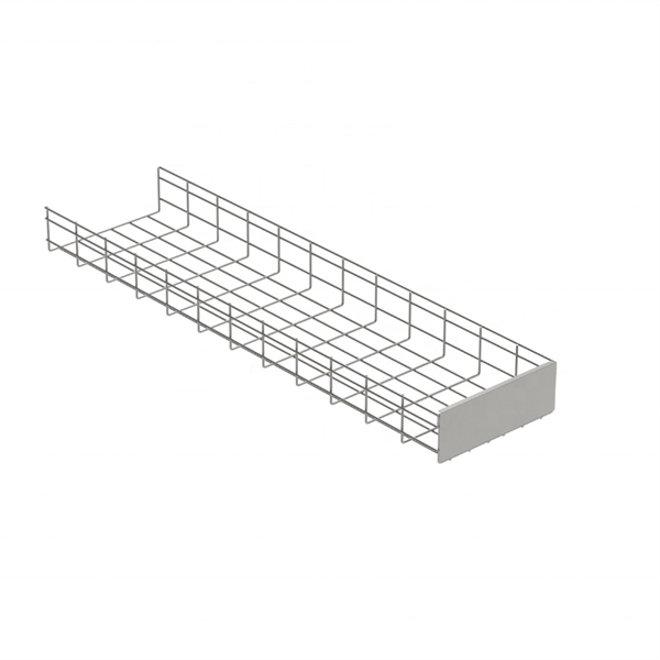
To calculate the cable tray capacity, multiply the width and height of the cable tray to find the total area, then multiply by the fill ratio. Divide this by the cross-sectional area of a single cable to find the capacity. Use the floor function to ensure you get a whole. Proper tray and ladder sizing ensures safe, efficient, and maintainable electrical installations in all engineering applications. IEC 61537 and IEC 60364 require evaluating tray dimensions based on cable quantity, type, and layout configuration. Below are industry-standard tray and ladder. Properly sizing your cable tray is critical for safety and compliance. Select Fill. A Cable Tray Capacity Calculator is an essential tool for electrical engineers, contractors, and project managers involved in the installation and management of electrical cables. This calculator determines the maximum number of cables that can be safely housed within a cable tray based on its. Enter the dimensions of the cable tray, the desired fill ratio, and the diameter of the cables to calculate the cable tray capacity. Set target fill, safety margin, and packing assumptions for projects across disciplines. Track counts, diameters, and weight to validate configuration quickly with live feedback. This calculator determines if your tray meets industry standards (typically 30-50% fill for alternating single-layer or 40-50% for random arrangement).
[PDF]