
Islamabad, October 31, 2024 – Jazz, Pakistan's leading digital operator and a member of the VEON Group, has taken a significant leap in advancing the nation's telecommunications infrastructure by deploying a 400G IP-based RAN Access Optical Network in collaboration with Huawei. Islamabad, October 31, 2024 – Jazz, Pakistan's leading digital operator and a member of the VEON Group, has taken a significant leap in advancing the nation's telecommunications infrastructure by deploying a 400G IP-based RAN Access Optical Network in collaboration with Huawei. Huawei Technologies and Transworld Associates announced the successful deployment of Pakistan's first 400G optical network, a major milestone in the nation's digital infrastructure development. The cutting-edge network spans 72 sites nationwide, underscoring both companies'. Islamabad: In a landmark step toward Pakistan's digital transformation, Huawei Technologies and Transworld Associates on Wednesday afternoon announced the successful deployment of the country's first 400G optical network, significantly enhancing connectivity across the China-Pakistan Economic. Huawei provided a 400G solution designed for high bandwidth and low per-bit cost. Key features include: a. A CDF network architecture enables smooth evolution to higher speeds (400G+ and beyond) while facilitating L-band expansion for enhanced capacity. Delivering 400G per wavelength, each fiber.
[PDF]

When it comes to testing fiber optic cables, a Visual Fault Locator (VFL) is an essential tool in your toolkit. A VFL is used to detect faults, breaks, or bends in fiber optic cables by emitting a bright red light that is visible even through the fiber's jacket. Let's dive into everything you need to know about mastering VFLs. In the. Finding a break in a fiber optic cable can be challenging but is essential for maintaining a stable network. Common Indicators of a Cable Break Signal. Here Kingfisher's experienced engineers share their experience in best practices and procedures for fiber optic testing related mostly to installation and maintenance. We hope that by sharing our knowledge, we will help grow our industry. Please enjoy & pass on these notes. The following are key methods and techniques used for optical fiber cable line failure positioning: Visual Inspection: Perform a visual inspection of the. Locating faults in fiber optic cables requires specialized tools and techniques. Look for dirt, scratches, or damage on the connectors. Clean. To ensure the quality and continuity of fiber optic services, it is essential to identify and locate fiber optic cable faults as quickly and accurately as possible. In this article, you will learn about some of the common methods and tools for fiber optic testing and troubleshooting.
[PDF]
Fiber-Mart offers most affordable high performance MEMS optical switches. The MEMS technology offers extremely low electrical power consumption, high durability (> 1x10^9 cycles), no stiction, and high resistance to shock & vibration. Sercalo's optical MEMS switches are the best choice for optical switches in Network supervision and optical test and measurement because they exhibit solid state reliability, ultra small insertion loss and long-term stability. Since 1999 Sercalo Microtechnology Ltd. supplies optical MEMS solutions. These MEMS single mode switches are designed to be easily integrated into optical systems. The switch is packaged to. MEMS-based switches offer high reliability that passed well over 10⁹ cycles of switching tests. The 1D motion MEMS mirror (in or out of the light path) offers low crosstalk or high on/off ratio, fault-safe latching, free space platform. The 2D. Or specify any custom connector requirement Download the Optosun Optical switch Mems PDF - Opens in new window. Orbray's MEMS (Micro Electro Mechanical System) Optical Switch are designed a small footprint package with providing low insertion loss, flat wavelength dependence loss (WDL), low polarization dependence loss (PDL) and performing less than 1ms/10ms switching speed. Well designed by the professional engineers, MEISU's capacitive MEMS switches are all featured with compact size, high channel count and long life time.
[PDF]

OSFP, or Octal Small Form-factor Pluggable, is a high-speed transceiver form factor designed for next-generation data center networking. Compared with previous generations of optical modules, OSFP is optimized for higher bandwidth, better thermal performance and denser port. Among the various 400G optical transceiver form factors, OSFP stands out as a next-generation form factor specifically designed for high-speed Ethernet, offering clear advantages. This article introduces the fundamental concept and key characteristics of 400G OSFP Ethernet optical transceivers, and. Optech, a Taiwan-based optical transceiver manufacturer, provides professional 400G OSFP and 800G OSFP solutions designed for AI, cloud, high-performance computing, data center and advanced networking applications. Understanding MSA is critical for compatibility validation, cost. As data centers transition from 400G to 800G interconnects, bandwidth demand, power efficiency, and thermal constraints have forced the industry to look beyond traditional form factors. Designed to support 400 Gigabit Ethernet transmission with improved thermal performance and higher power capacity, OSFP modules are widely adopted.
[PDF]
As an essential component of optical fiber communication, optical modules are optoelectronic devices that facilitate the conversion between optical and electrical signals during the transmission process. Operating at the physical layer of the OSI model, optical modules are core devices in optical. The optical module serves as a crucial component in optical fiber communication systems, operating at the physical layer, which is the lowest layer in the OSI model. Classification of Optical Module: Distinguished according to function, package form, transmission rate, wavelength. In the era of 5G, AI, and high-speed data centers, optical modules serve as the core bridge for converting electrical signals to optical signals (and vice versa), enabling fast, reliable data transmission across networks. They are used in fiber optic communication systems to transmit data over long distances with minimal loss and interference. These modules typically consist of a laser or LED transmitter, a.
[PDF]

An ideal optical splitter will distribute the light power according to mathematical principle. This is because each of the 8 output ports of the splitter will receive only one-eighth of the. Thorlabs' Single Mode 1x8 Fiber Optic Planar Lightwave Circuit (PLC) Splitters allow a user to split a single input signal evenly into eight output signals, which is ideal for passive optical networks (PON) and other high-channel-count applications. 1×8 splitter means it takes one input fiber and splits the signal into eight outputs. It doesn't need power — it's passive! Great for sharing one signal with many devices, like in FTTH (Fiber To The Home) networks. But light doesn't just split for free. Sharing means each output gets less than the. If we operate with absolute gains measured in relation to 1 milliwatt (mW), they are expressed in dBm, and are calculated as follows: Power Level (dBm) = 10 lg ( mW / 1 ) For “household” needs, in order not to calculate mW to dBm and vice versa every time, here's a ready-made correspondence table:. For instance, a 1:8 splitter ratio signifies an equal distribution of incoming optical power among eight output ports, with each port receiving 1/8th of the total power. It has one input port and eight output ports, making it ideal for applications where a signal needs to be.
[PDF]

Remove and reinstall the optical module. If the fault persists, replace the optical module with a normal one of the same type to check whether the optical module is faulty. The optical module is faulty or not securely installed. The device management or driver software has a bug. If the optical module is installed on a GE port, run the display interfaceGigabitEthernet x/x/x command to view port information when the optical module is inserted, including the rate and wavelength. Have you ever dealt with sudden network drops from faulty optical modules? Issues like this cannot only break communications, but they can really jeopardize business continuity. Understanding how to troubleshoot and prevent a failing optical module is vital for good network stability. This article. Huawei switches using non-certified optical module may not be able to read the information, can not guarantee the accuracy of the information read, recommend the use of Huawei certified optical switch module. Page 5 Changes in Issue 01 (2017-09-10) This issue is the first official release. The software version of this issue is V800R010C00. Issue () Huawei Proprietary and Confidential Copyright © Huawei Technologies Co. Page 8 40º C if a 40º C if a at 40º C if a single fan single fan single fan. The device cannot display any optical module information but services are running normally.
[PDF]

In telecommunications, a base station is a fixed transceiver that is the main communication point for one or more wireless mobile client devices. It further connects the device to other. A communication base station is composed of a computer room, base station, antenna, feeder line (transmission line between transmitter and antenna), and supporting equipment. The antenna is at the top of the signal tower, and below the tower is a computer room. Along with increased capacity demands driven by the explosion of cloud and connected device growth, engineers need interconnects that enhance the design. A base transceiver station (BTS) or a baseband unit (BBU) is a piece of equipment that facilitates wireless communication between user equipment (UE) and a network. UEs are devices like mobile phones (handsets), WLL phones, computers with wireless Internet connectivity, or antennas mounted on. Fiber Optic Cables: High-speed fiber optic cables connect the BBU to the RRUs (RE part). Signal Transmission: The optical signals carry data, control, management, and synchronization information. Topology: The BBU and multiple radio heads can be connected in cascade or star configurations. The rise. The design investigates the possibilities of Free-Space Optical (FSO) communication systems and MilliMeter-Wave (MMW) technologies operating at 60. Although these technologies are highly effective and have a high throughput, they are nevertheless vulnerable to weather phenomena like rain.
[PDF]

Insertion loss tells you how much weaker the signal becomes after passing through the splitter. Let's say you have a laser output at 0 dBm (which is 1 milliwatt of optical power). If you use a 1×8 splitter with ~10. 5 dB of insertion loss, the power at each output would be: 0 dBm – 10. 5. Enter excess loss from the splitter datasheet for your wavelength. Add connector and splice quantities with realistic planning losses. Include any additional component losses and an engineering margin. Enable power budget to estimate received power and margin. Press Calculate to show results above. Understanding optical splitter loss isn't just about plugging numbers into a calculator. It's about knowing what factors contribute to that loss, how manufacturers specify it, and how it impacts the overall performance and reach of your network. Ignore it, and you might find your signal too weak to. Optical insertion loss refers to the signal loss resulting from the insertion of components such as connectors or splices in an optical fiber system. Common ratios: For cascades, add losses and validate margin using the Optical Budget tool. This Fiber Optic Splitter Insertion Loss is the splitter devices loss, Considering fiber connectors or connectors+adapter insertion loss in LGX, The fiber splitter IL would be a little bigger. To make clear the basic ftth fiber splitter loss in performance, You can refer to the below loss chart.
[PDF]

RFP Publishing Period: from November 12th, 2025 to 14h00, November 26th, 2025 (GMT+6:30), during MYTEL's office hours — from 8h00 to 17h30, Monday to Friday. 61-63, Zoological Garden Rd., Dagon Township, Yangon, Myanmar. We have identified 63 global optical fibre cable tenders from the public procurement domain worldwide. View the latest global tenders for optical fibre cable from Africa, the Americas, Asia, Australia, Europe, the Middle East, and other countries. Find global tender information, RFPs, RFQs, ICBs. Mytel Announcement on Invitation to Bidding No. RFP 134/2025/MYTEL-OPTICALCABLE – “Purchase OPTICAL CABLE for Mytel”. Requesting Party: TELECOM INTERNATIONAL MYANMAR CO., LTD. Tender For Provision of Fiber-optic internet services for OCHA in Sudan., communication channel rental services (fiber-optic communication channel rental services in the city of makinsk. Please click here to see the Current Opportunities. Procurement of Furniture and Equipment for the support to operationalize Public Procurement Act. Are you searching for the latest Fiber Optic Cable Tenders from trusted sources across the globe? Tender Impulse is the go-to tender website for businesses seeking verified and timely updates on public tenders, government tenders, and business tenders in a wide range of sectors.
[PDF]

No, a 10G SFP (Small Form-factor Pluggable) module is designed to operate at 10 Gigabits per second (Gbps) and is not compatible with a 1 Gigabit per second (Gb) port. Therefore, a 10G SFP module will not work. When SFP optical module is inserted into the SFP port of Gigabit switch with fiber optic patch cable or copper cable, it can realize different distance transmission. For example, the maximum transmission distance is 160 km when using SFP1G-ZXC-55 optical module and LC duplex fiber patch cable, and. 10 Gigabit Ethernet (10GE, 10GbE, or 10 GigE) is a group of computer networking technologies for transmitting Ethernet frames at a rate of 10 gigabits per second. It was first defined by the IEEE 802. For example, when using the AE-SFP-ZX160 optical module and LC duplex fiber optic patch cords, the maximum transmission. Can 1G SFP optics work with 10Gb SFP+ ports on a 10Gb switch, or vice versa? This comprehensive guide reveals the intricacies of SFP and SFP+ compatibility and provides useful solutions for network switch users. Can 1G SFP Optics Run at 10G SFP+ Port? Can 10G SFP+ Optics Run at 1G SFP Port? Can. Small form-factor pluggable or SFP Modules can be described as compact and hot-pluggable hardware that connects various networking devices such as servers, routers, and switches. Networking standards, including Ethernet, Fiber Channel, and SONET, are also used with the SFP modules, broadening their.
[PDF]

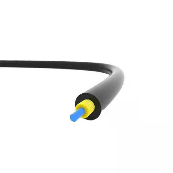
This article will give you an overview of the use cases for fiber-optic networking, some of the terms used in fiber networking, and suggestions for setting up a fiber network. Once you understand the basic concepts, you can check out my Recommended Equipment section toward. Fiber tapping is a network tap method that extracts signal from an optical fiber without breaking the connection. Tapping of optical fiber entails diverting some of the signal being transmitted in the core of the fiber into another fiber or a detector. Fiber to the home (FTTH) systems use beam. Optical fiber is a technology used to transmit data by sending short light pulses along a long fiber, which is typically made of glass or plastic. In optical fiber communication, metal wires are preferred for transmission because the signals travel more safely. Optical fibers are also resistant to. Photo: Light pipe: fiber optics means sending light beams down thin strands of plastic or glass by making them bounce repeatedly off the walls. This is a simulated image. Note that in some countries, including the UK, fiber optics is spelled "fibre optics. " If you're looking for information online. This manual covers everything about fiber optic cables, how they work, where they are used, and what is new in this area of technology. The choice of fiber optic cable depends on the specific needs of the application, as well as the.
[PDF]
Optical cable junction boxes play a crucial role in connecting and protecting optical fibers, directly influencing the quality and lifespan of optical cable routes. Optical cable splice boxes protect the splicing parts of optical fibers from various hazards, such as water seepage due to adverse. Optical cable junction boxes play a crucial role in managing and organizing fiber optic networks. It serves as a termination point for fiber optic cables, providing protection and distribution of the optical fibers while ensuring efficient signal transmission. Utilizing an optical junction box can significantly enhance your. Optical cable splice box is a popular name, its scientific name is optical cable splicing box, also known as optical cable splicing package, optical cable splicing package and gun barrel. These boxes are designed to house and protect fiber optic splices and terminations, ensuring that the delicate fibers are safeguarded from.
[PDF]

