
A lighting control module operates as the central controller for a lighting system. It receives input from switches, apps, or sensors and regulates electrical flow to connected lights. Depending on the setup, it adjusts brightness, color temperature, or full lighting scenes. It acts as a bridge between your physical lighting fixtures and the smart systems that manage them. Instead of relying solely on traditional wall switches, you can control your lights via remotes, mobile or web apps. A lighting control module is an essential component in a lighting control system that manages how lights are powered, dimmed, or switched on and off. Think of it as the “brain” that receives commands—either from a manual switch, a sensor, or a building automation system—and translates them into. A lighting control module is a smart device that manages lighting circuits, adjusting brightness, automating schedules, and responding to sensors. It enhances comfort, efficiency, and ambience in homes and commercial spaces. Explore the multifaceted benefits and applications of lighting control modules, from home automation to industrial. These modules are designed to communicate with various sensors, switches, and control panels, making lighting adaptable to different environments and user preferences. It enables precise management of lighting systems, allowing for adjustments in brightness, color, timing, and even integration with other smart devices. This innovation.
[PDF]

Therm-X is a specialist in thermal systems, temperature sensors, heaters, thermocouples, controllers and resistance temperature detectors (RTDs) for renewable technologies. We have designed and co-developed temperature sensitive process equipment for solar, fuel cells, and other. In this comprehensive guide, you'll discover how temperature monitoring systems optimize photovoltaic power plant performance. We. Our Temperature Sensors ensure reliable and accurate temperature readings in all conditions. Constructed with premium materials and calibrated for precision, these sensors are designed for durability and stability, providing dependable performance over time. This TI Design addresses the key need of a highly cost-optimized monitoring and communication subsystem for solar module level power electronics (MLPE). This design. In addition to the standard line, ACS is able to offer customized solutions thanks to its more than 60 years of experience in designing customized environmental simulation chambers, its technical know-how and the close attention given to the requests of all our customers. Example of a chamber. We have designed and built simple custom temperature control solutions from single zone 150W panels up to large +850kW multi-zone/multi-circuit panels with a full HMI and plant-wide DCS integration. Below are some custom features we can add to your panel. Contact us to discuss your specific.
[PDF]

In part one of GIGABYTE Technology's latest Tech Guide, we explore the industry's most advanced cooling solutions so you can evaluate whether your data center can leverage them to get ready for the era of AI. 9 thermal guidelines applied to AI data center cooling — H1 high-density class, B200/GB200 implications, and what's coming in the next revision. Liquid. As Artificial Intelligence (AI) and High-Performance Computing (HPC) workloads drive rack densities beyond 50kW, traditional air cooling is reaching its physical and economic limits. Liquid cooling—specifically Direct-to-Chip (D2C) or Cold Plate technology—has emerged as the standard solution for. Modern AI accelerators have dramatically increasing power requirements, with TDPs rising from 300W (V100) to over 1,400W (MI355X) Heat Output = 700W × 0. 5W thermal BTU/hr = 696. Traditional air-cooling methods are struggling to keep pace with cooling the data center. Compute infrastructures for training large AI models are similar to high-performance computing (HPC) systems, which have long been used for demanding tasks in fields such as engineering, scientific research and finance. Industry insiders familiar with the natural progression of the modern data center will.
[PDF]

This paper will review the development of fiber-optic high-temperature sensors over the last 30 years, presenting their design and fabrication methods according to sensing type and typical temperature measurement performance. The full paper consists of eight sections. Fiber-optic high-temperature sensors are gradually replacing traditional electronic sensors due to their small size, resistance to electromagnetic interference, remote detection, multiplexing, and distributed measurement advantages. This paper reviews the sensing principle, structural design, and. Luna's Optical Backscatter Reflectometer (OBR) products are based on OFDR and provide a level of detail and precision not available with the prevailing fiber optic diagnostic tool - the optical time domain reflectometer (OTDR). OBR systems map out loss along a single-mode fiber (SMF) or multi-mode. breadth and most comprehensive solutions for optical communications test products to be found in one place. Corning's High Temperature Fibers are designed for applications requiring improved fatigue resistance, high usable strength, and excellent resistance to higher temperatures and hydrogen permeation. Thus, wireless communication -situ processing of data would combined with in significantly improve the ability to include sensors into high temperature systems and thus lead toward more intelligent engine systems. NASA Glenn Research Center (GRC) is presently lea, communication systems,ding the.
[PDF]
CamdenBoss PCB terminal blocks come in a variety of sizes and styles. They can accept a wide range. • Rising clamp PCB terminal blocks give excellent repeatable clamping performance. Four mounting holes are provided. Molex's Temperature Sensor Cable Assemblies are available in custom and off-the-shelf solutions with a variety of beta values, resistances, lengths and temperature ranges to meet a diverse range of applications. Molex also offers custom options of these assemblies to ensure the specifications can meet exact design requirements. Thermocouples are made from two dissimilar metals joined at a hot junction and generate a millivolt signal as the temperature changes, while RTDs and thermistors exhibit a change in their resistance. These compact assemblies include a ring terminal, thermal conductive epoxy, and/or a Micro-Lock Plus connector to provide a market-ready solution for temperature.
[PDF]
We describe a theoretical and experimental study of an intensity-based, dual-wavelength referenced fiber optic temperature sensor utilizing temperature-induced spectral shifts of optical thin-film interference coatings, deposited on a sensor fiber end. We present coating design considerations that. This study proposes the development of a dual-wavelength optical fiber sensor (DWOFS) that integrates two optical fiber structures in a multimode transmission line to measure the refractive index and temperature of a liquid concurrently. One structure is based on a refractive index sensor that. ter. The dual-wavelength fiber laser has a ring cavity composed of two FBGs with central wavelengths of 1550. Through monitoring the wavelength shift and the output power difference of the dual-wavelength fiber laser, the simultaneous measurement for RI and temperature is. To improve the sensitivity measurement of temperature sensors, a fiber optic temperature sensor structure based on the harmonic Vernier effect with two parallel fiber Sagnac interferometers (FSIs) is designed, and theoretical analysis and experimental testing are conducted. The FSI consisting of. Fiber-optic high-temperature sensors are gradually replacing traditional electronic sensors due to their small size, resistance to electromagnetic interference, remote detection, multiplexing, and distributed measurement advantages. This paper reviews the sensing principle, structural design, and.
[PDF]
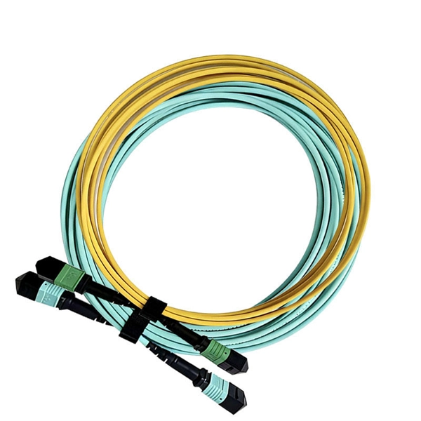
A cable management rack is designed to route, protect, and organize copper and fiber cables inside network cabinets. Beyond keeping cables tidy, a well-structured cable manager reduces cable stress, improves heat dissipation, and ensures bend-radius compliance for data transmission. This article provides a clear technical view of cable management racks, their structures, and how to select the right solution for modern networks. Cable management in server racks simply refers to organizing, routing, and securing power and data cables so they stay neat, accessible, and. Simply put, a cable rack is a structured set of shelves designed to organize, protect, and manage cables in various settings. These racks range from simple, affordable options to complex, high-capacity models that accommodate a vast number of cables. The benefits of using cable racks are numerous. Horizontal cable management is a cornerstone of efficient IT infrastructure, ensuring that server racks and enclosures remain organized, accessible, and functional., Ethernet, fiber optic, coaxial). At its core, it aims to: Minimize cable tangling, kinking, and wear. Simplify troubleshooting and maintenance. As businesses increasingly rely on robust network infrastructure, proper cable organization becomes critical for.
[PDF]
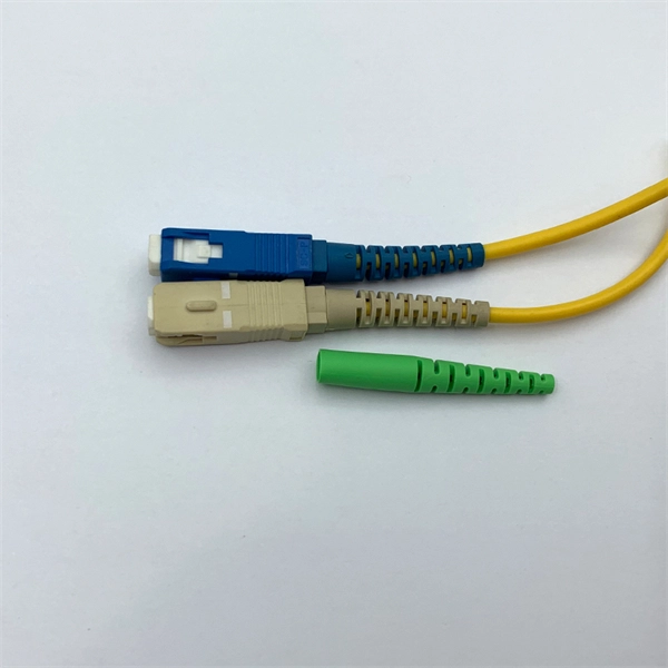
In a fused fiber splitter, the input fiber is aligned with the fused region, which causes the optical power to be divided between the output fibers. The tapering process gradually guides the light from the input fiber to the output fibers, resulting in a proportional split of the. A fiber-optic splitter, also known as a beam splitter, is based on a quartz substrate of an integrated waveguide optical power distribution device, similar to a coaxial cable transmission system. The optical network system uses an optical signal coupled to the branch distribution. It plays a crucial role in enabling multiple devices to share a single fiber optic connection, maximizing the utilization of the available. Essentially, a fiber optic splitter performs the following actions: Light Enters: Light travelling through a fiber optic cable enters the splitter. Passive Separation: Inside the splitter, the light is split into multiple separate beams using optical components. Conversely, it can also combine multiple signals into one. Its primary role is in Passive Optical Networks (PON), which are the foundation of. A fiber optic splitter is a passive optical component that divides a single incoming optical signal into two or more outgoing signals, or combines multiple incoming signals into one. However, modern splitters can have multiple inputs and outputs, allowing for the distribution of a single signal to dozens of receivers. The internal workings of a passive.
[PDF]

Learn how to wire a frequency converter (VFD) for start and stop control using an electric pressure gauge in this detailed tutorial. It is used to ensure that the panel is wired correctly and safely, and to troubleshoot any problems that may occur. Water pump control. Notes or instructions that make the job easier and ensure safe operation. 1 General description Control CUE is a series of complete control cabinets with a builtin Grundfos CUE frequency converter and all necessary electrical components. Sections 1-7 provide the information necessary to be able to install and start up the products in a safe way. Output filters Thanks to the startup guide in the CUE, the installer can quickly Operating modes set central parameters and put the CUE into operation. This. UNINTENDED START. When the frequency converter i erminal 18 open). To prevent unintended motor start: press ut sing the product. Improper use of the product can cause personal injury and damage to property, and may to the equipment. This includes any modification to the equipment or use of.
[PDF]

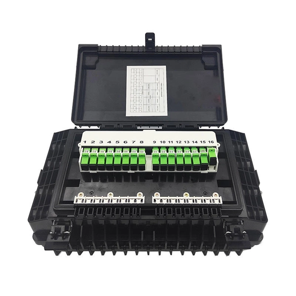
The core function of any distribution board is to allow individual circuits to draw power from correctly rated circuit breakers and for those circuits to be isolated without causing a disruption to the rest of the supply. With the continuous improvement of people's living standards, the requirements for electrical equipment are higher and higher, and the functions are more and more complete. But now the traditional distribution mode is still used in the distribution box of building users, and the single control is. kage protection units used to distribute electrical power to numerous individual circuits or consumer points. The board typically has a single incomi g power source and includes a main circuit breaker and a residual current or earth leakage protection device. Failure to strictly adhere to the warnings and cautions as well as the installation instructions may result in serious personal. These innovations improve system reliability, safety, and operational efficiency by enabling real-time monitoring, predictive maintenance, and remote control. Background Traditional distribution boxes are difficult to implement remote monitoring due to. Electric distribution companies have tens of thousands of transformation centers that perform the function of distributing electric power, taking meter readings from supply points, and that are responsible for maintaining and ensuring all the elements involved operate correctly. In order to fulfill.
[PDF]

Plug the control cable of Fan 1 to the Quick-Connect box. Use cable ties to mount the control wiring to the wall panel ensuring it is taut, secure, and supported. The white wire from the fixture is connected directly to the source neutral wire, either at the fixture box or through a splice at the switch box. In some household circuits, the white wire may also be. Ceiling fan installation is electrically simple (15A circuit, 14 AWG) but the critical requirement is a fan-rated electrical box per NEC 314. A standard light fixture box cannot support the weight and vibration of a ceiling fan. Route and fasten harness to the bulkhead wall after it has been plugged into the. Check each product page for other buying options. Price and other details may vary based on product size and color. Shop products from small business brands sold in Amazon's store. Learn more. A ceiling fan is a dynamic appliance requiring specialized support beyond what a standard junction box provides. Installation focuses on replacing the general-purpose box with a fan-rated version secured directly to the ceiling framework. New Work Fan Rated Electrical Ceiling Box with Captive Nails (B520A-CFB) Carlon 1-Gang 20 cu.
[PDF]
To investigate the optimal radial-arranged-position of the optical fiber in the cross-linked polyethylene (XLPE) power cable, the fibers were arranged into three positions, including segmental conductor c.
[PDF]

A laser diode is a semiconductor device that emits light when an electric current is passed through it. The light emitted by it is very intense and narrowly focused, making it an ideal source of light for use in optical fiber communications and laser printers. In this article, we will discuss the. The optical power value, Po, is the most basic characteristic of a laser diode. This parameter is defined as the light output intensity in the case that a specific current is applied to the device in the forward direction, and is typically expressed in units of W. It operates similarly to a light-emitting diode (LED) but produces a focused, monochromatic, and coherent beam of light. These gadgets track down wide applications because of their proficiency and minimal size. When electric current flows through the p-n junction, the gain is. A Laser Diode is a semiconductor device similar to a light-emitting diode (LED). It uses p-n junction to emit coherent light in which all the waves are at the same frequency and phase. They consist of a p-n semiconductor junction, with a forward bias voltage applied.
[PDF]

