Equinox blind spot system may show sensor errors or intermittent mirror detection failures. The 'Side Detection Temporarily Unavailable' warning often indicates sensor blockage or malfunction. Check for physical. That “Service ESC” light means your Equinox's Electronic Stability Control system has detected a problem. This is the system that helps keep your car planted and stable when road conditions get dicey, think wet pavement, sharp turns, or icy highways. When it's not working properly, you lose that. I was leaving an event this evening, and as I was stuck in bumper to bumper traffic my car popped up with a message in the display that the Side Detection System was unavailable (2018 Chevy Equinox Premier). And sure enough, the blind spot detection stopped working. Of course this had to happen at. The time now is 12:49 PM. 2025 chevrolet equinox Technical Service Bulletins (TSBs). These sensors may be dirty, obstructed, or experiencing communication problems. track control etc plus random service messages. 1 click faint light on then off. happened all of a sudden. seems to run ok when it. This sub-reddit is dedicated to everything related to Chevy vehicles: driving, racing, collecting, and more. Equinox Blind Spot Sensors - Where are they? Hi! I just bought an equinox 4 days ago, and suddenly my blind spot warning lights in my side mirrors are coming on all the time when there.
[PDF]

Fiber-optic communication is a form of optical communication for transmitting information from one place to another by sending pulses of infrared or visible light through an optical fiber. The light is a form of carrier wave that is modulated to carry information. Fiber is preferred. This method encodes data into light signals by modulating properties like wavelength, phase, and polarization. The light signals propagate to the receiver through the fiber optic cable. Optical fiber communication relies on the properties of light from the electromagnetic spectrum. By optimizing. These strands, known as fibre optic cables, have revolutionised telecommunications because they transmit information using pulses of light. Unlike copper wires, which send electrical signals and suffer from resistance and interference, fibre optics offer orders of magnitude more bandwidth and. Optical Fiber Light Transmission commonly known as fiber optics is a technology that utilizes thin transparent fibers made of glass or plastic to transmit data and information using the light signals. This technology forms the backbone of global data transfer due to the immense bandwidth capacity of light. Light waves possess a frequency spectrum vastly wider than. Less costly per meter. Lower transmitter launching power. Less susceptible to electromagnetic interference. Flexible use in mechanical and medical imaging systems. Automotive and many other industories.
[PDF]
Optical fibers can be used as sensors to measure strain, temperature, pressure and other quantities by modifying a fiber so that the quantity to be measured modulates the intensity, phase, polarization, wavelength or transit time of light in the fiber. Sensors that vary the intensity of light are the simplest, since only a simple source and detector are required. A particularly useful feature of intrinsi. OverviewA fiber-optic sensor is a that uses either as the sensing element ("intrinsic sensors"), or as a means of relaying signals from a remote sensor to the electronics that process the signals ("extrinsic s. Extrinsic fiber-optic sensors use an, normally a one, to transmit light from either a non-fiber optical sensor, or an electronic sensor connected to an optical transmitter. A major benefit of e. It is well-known the propagation of light in optical fiber is confined in the core of the fiber based on the total internal reflection (TIR) principle and near-zero propagation loss within the cladding, which is very important f.
[PDF]
High-definition temperature sensing based on the natural Rayleigh backscatter in optical fiber delivers a virtually continuous line of temperature measurements with sub-millimeter spatial resolution. 1. Map temperat.
[PDF]
This paper describes the optimal design of a miniature fiber-optic linear displacement sensor. It is characterized by its ability to measure displacements along a millimetric range with sub-micrometric resolution. The sensor consists of a triangular reflective grating and two. displacement, pressure, temperature and electric field. Recently, high precision fiber displacement sensors have received significant attention for applications ranging from industrial to medical fields that include reverse engineering and micro-assembly (Laurence et al. The design and adaptability of Cleveland Electric Labs linear and rotary displacement sensors provide optimum measurement possibilities for a wide variety of applications. CEL s linear sensor has a travel range from less than 1 inch up to 18 inches with an accuracy of 0. 005 and our rotary sensor.
[PDF]
Interferometric fiber optic current sensors (FOCS) employ circularly polarized light traversing a closed loop path around an electrical conductor's current-generated magnetic flux, which reflects off a mirror. The light experiences a reciprocal phase shift as the refractive index, and effective path length, is modulated by the presence of a magnetic field, which optically induces circular. OverviewA current sensor (FOCS) is a device designed to measure. Utilizing a single-ended optical fiber wrapped around the current conductor, FOCS exploits the (. As FOCS are resistant to effects from magnetic or electrical field interferences, they are ideal for the measurement of electrical currents and high voltages in or other environme.
[PDF]

FOCS systems can measure currents up to 700 kA. They offer a practical alternative to traditional Hall-effect sensors, using a lightweight, clamp-on design that allows installation without opening bus bars — reducing time and complexity. A fiber-optic current sensor (FOCS) is a device designed to measure direct current. Utilizing a single-ended optical fiber wrapped around the current conductor, FOCS exploits the magneto-optic effect (Faraday effect). The result is exceptional accuracy and reliability. Based on the magneto-optic effect, FOCS can measure uni- or bidirectional DC ering signal disturbance immunity available for complex industrial processes. It is unaffected by stray magnetic fields at the plant, s. The FS205 is a high precision DC high current measurement device based on the Faraday Magneto-optical Effect and the Ampere Loop Theorem. The sensing optical fiber is fixedly mounted on the high current busbar through a skeleton and forms a closed optical fiber loop. They are immune to electromagnetic interference (EMI) and do not suffer from magnetic saturation, which improves accuracy, simplifies installation, and enables reliable digital. A fiberoptic sensor that uses diverse fiber units to support various applications in virtually any environment. These are reliable and easy-to-use devices that have high power, can automatically adjust to real-time conditions, and have a straightforward display that eliminates any guesswork.
[PDF]
The Fiber Optic Sensors market was valued at USD 2,560. 00 million in 2018, reached USD 3,547. Starting at USD 2. By 2035, it is projected to reach USD 6. 3% throughout the forecast period from 2026 to 2035. I need the full data tables. As per Market Research Future analysis, the Fiber Optic Sensor Market Size was estimated at 3. 08 USD Billion by 2035, exhibiting a compound annual growth rate (CAGR) of 10. 22% during the. Fiber optic communication relies on light waves, which are difficult to intercept or tamper with, making fiber optic sensors an attractive option for industries that require secure data transmission. I need the full data tables, segment breakdown, and competitive landscape for detailed regional analysis and. Global Fiber Optic Sensors Market Research Report By Type (Intrinsic, Extrinsic), By Component (Receiver, Transmitter, Fiber Optic Cable, Optical Amplifier), By End-User (Transportation, Medical, Defense, Industrial, Oil and Gas), By Region (North America, Europe, Asia Pacific, Latin America. Global Fiber-Optic Sensors Market Size By Type of Fiber-Optic Sensors (Intrinsic Fiber-Optic Sensors, Extrinsic Fiber-Optic Sensors), By Sensing Parameter (Temperature Sensors, Pressure Sensors), By Application Sector (Aerospace and Defence, Oil & Gas), By Technology (Fibre Bragg Grating.
[PDF]
FiberFin offers products specifically designed for the wide variety of sensor applications that POF is used in. There are three common methods for measuring external forces using plastic optical fiber. Optical fiber sensors have revolutionized the way we measure and monitor various physical and chemical parameters in different industries. These sensors utilize the properties of light to detect changes in the environment, making them highly sensitive and accurate. In this article, we will explore. Fiber Optic Sensors for Plastic Components by Application (Electronic Product, Automobile, Industrial Equipment, Others), by Types (Single-Tube, Double Tube, Multitube), by North America (United States, Canada, Mexico), by South America (Brazil, Argentina, Rest of South America), by Europe (United. While fiber optic cables can be used to connect remote sensors to electronic loggers or signal processors the same way that copper wires can, they can also be used as sensors themselves.
[PDF]

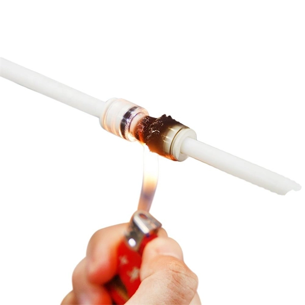
Connecting a fiber patch cord involves carefully inserting it into the appropriate adapter after ensuring the connectors are clean. The process may differ slightly depending on the type of connector. The core process involves two main stages: preparation and insertion. Planning helps you pick the right cord for your network. Be gentle when you handle the cord. Fibre patch cords last longer and are tougher than copper cables. They also protect better from interference. Look at the table below to compare:. Connecting a fiber optic patch panel may seem daunting at first, but if you follow the right steps, it's actually quite simple – and can even be done in just a few minutes. Preparation: Before. Fiber Optic Transceivers: For converting signals between optical and electrical form. Cleaver: For precisely cutting the fibers. Safety Equipment: Gloves. In today's high-performance networks, fiber optic patch cables are the lifelines that ensure smooth data flow across switches, servers, and routers. Even the most advanced optical transceivers can only perform at their peak when paired with properly installed, clean, and precisely managed fiber. Correct patch-cord installation is essential for maintaining low insertion loss, stable return loss, and long-term reliability in both indoor and outdoor fiber networks. Proper handling, routing, cleaning, bend-radius management, and connector alignment ensure that the optical link meets design.
[PDF]
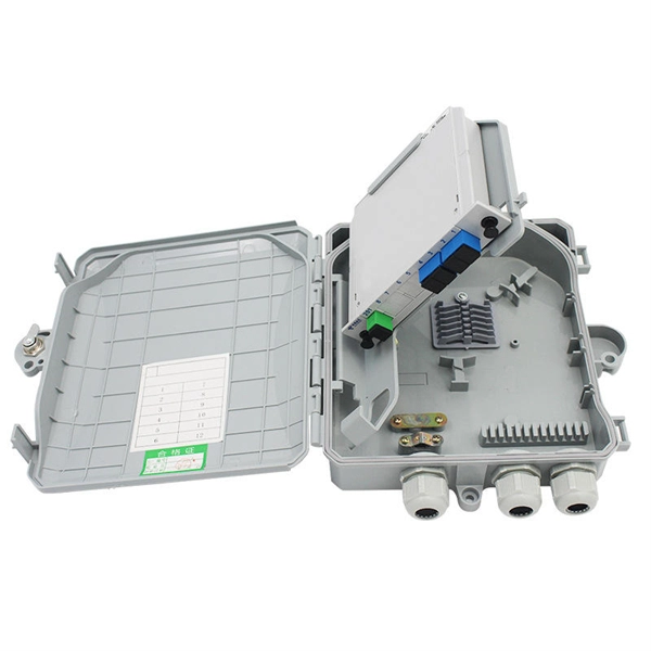
Learn how to install a fiber optic termination box step-by-step for FTTH projects. Covers mounting, splicing, routing, labeling, and testing for indoor/outdoor use. Installing a fiber optic termination box is one of those jobs that looks simple on paper, but it's easy to do. A common question we receive is: How do you use a fiber-optic termination box? We recommend using a termination box if you're ordering an assembly with more than two strands. It helps keep your connectors free from contamination and dust, while also keeping your assembly neat and organized. Check. A Fiber Termination Box, also known as a Fiber Distribution Box, is a crucial component in fiber optic networks. They also feature resistance to moisture, impact, chemical exposure. Whether you're a network technician, IT professional, or simply looking to understand fiber optic networks better, this guide will provide you with the essential knowledge for working with fiber termination box.
[PDF]
Scientists have demonstrated a new fiber-optic sensing method that detects strain and displacement by reading interference patterns directly in the electrical spectrum of a photodetected signal. They used a polymer optical fiber-based single-mode–multimode–single-mode (SMS). Electrical-domain interference in polymer optical fibers offers a simpler route to fast sensing without conventional optical-spectrum analysis. This image summarizes the newly demonstrated sensing principle. Published in IEEE Sensors Journal on April 27, 2026. Researchers have unveiled a groundbreaking fiber-optic sensing technique capable of detecting strain. This review focuses on MMI fiber sensors for nonconventional physical variables, including mechanical, electromagnetic, chemical, and optical, covering around fifteen years of work in the field. Finally, by the end of this paper, we also review some new trends of MMI-based schemes based on polymer.
[PDF]

This GAOTek Multi-Wavelength Optical Light Source is a portable device which provides a single button switch operation for the following multi-wavelength output options: 650 nm, 850 nm, 1300 nm, 1310 nm and 1550 nm. This product is already in your quote request list. Overview. Unlock exceptional illumination versatility with the Prizmatix CombiLED high-power multi-wavelength LED illuminator engineered for microscopy and a wide range of scientific applications that demand intense, precisely controlled light across multiple discrete wavelengths. The CombiLED Light Engine. For nearly 30 years, RPMC's selection of Multi-Wavelength Lasers has set the standard for affordable precision across a wide range of applications, from defense to medical, industrial, and research with 1000's of successful units in the field. We understand that every application has unique. Multiple LED sources can be efficiently combined into a single output beam, and offer major advantages such as long life-time, easily tunable spectrum, high power stability, and ultra-fast switching (on the microseconds level) without using moving mechanical components. Multi-Wavelength Collimated. Sirchie provides the industry's best multi-wavelength forensic alternate light sources to the global law enforcement community. They provide a more complete range of wavelengths to cover more of the UV to IR spectrum for many application areas The CS-16-500W CrimeScope was designed for those.
[PDF]