An optical line termination (OLT), also called an optical line terminal, is a device which serves as the service provider endpoint of a passive optical network. It provides two main functions: to perform conversion between the electrical signals used by the service provider's equipment and the fiber optic signals used by the passive optical network.to coordinate the multiplexing between the conversion. FeaturesOLTs include the following features: • A downstream frame processing means for receiving and churning an cell to generate a downstream frame, and converting a parallel dat. Most vendors integrate an entire fiber optic management system for ISPs to manage OLTs as well as client ONTs and as such are not interoperable. • • BT-PON.
[PDF]
According to a recent study by the Fiber Broadband Association and RVA, 76. 5%) are now serviceable by fiber—an increase of 13% in 2024. By 2028, fiber is expected to reach 80% of U. Ultra-low loss (ULL) fiber directly addresses this issue, allowing data to travel farther with fewer interruptions. By minimizing signal loss, ULL fiber makes it possible to build high-capacity, long-haul networks that can support growing global demand. ULL fiber delivers clear advantages for. When viewed within its broader parent sector, the Communications Hardware market, which is expected to reach about $1,018 billion by the same year, fiber optics will comprise roughly 1% of this larger segment. Further, in the context of the overall Information Technology industry anticipated to hit. Gerald. As the industry looks ahead, six major trends are shaping the future of fiber.
[PDF]

Search by part number or description such as CAT5, CAT6, OSP, etc. Sort by any of the table headers. Use the drop down menu to filter by product category and type. Sort by any. Welcome to the Corning LANscape® Solutions Product Drawings Resource Center, your complete source for our optical hardware component drawings. The two-dimensional and isometric hardware products drawings are available in PDF (Adobe® Acrobat®), DXF (AutoCAD®), VSS (Visio® Stencil) formats, and. Free CAD and BIM blocks library - content for AutoCAD, AutoCAD LT, Revit, Inventor, Fusion 360 and other 2D and 3D CAD applications by Autodesk. CAD blocks and files can be downloaded in the formats DWG, RFA, IPT, F3D. You can exchange useful blocks and symbols with other CAD and BIM users. When possible we have included both linear and nonlinear cable models for your use as appropriate. The use of a linear cable model may be acceptable for calculating loads and sags in an as-built situation such as joint use applications, or when linear elastic behavior and nominal creep are desired. The two linetypes are shown below. The appearance is similar but slightly different. Does anyone have such a code that they could share with me? I struggled for an hour or so and came up with this. There is a small gap on the left side of the circle.
[PDF]

Compared to conventional metallic cables, optical fiber provides an advantage of low loss (~ 0. 2dB/km) and wide bandwidth (several hundred MHz to THz) to enable long-distance, high-capacity communication. Fiber-optic communication is a form of optical communication for transmitting information from one place to another by sending pulses of infrared or visible light through an optical fiber. The light is a form of carrier wave that is modulated to carry information. Fiber is preferred. It was almost a century later before optical-based communication was put to practical use, thanks in large part to the invention of optical fiber and lasers. A laser's stable, highly directional beam of light (emitted from tiny semiconductor windows that measure just a few hundred thousandths of a. In 2020, we celebrated the 50th anniversary of the invention of low-loss optical fiber — an innovation that has transformed the way we connect and that lies at the cornerstone of our communications revolution. In a Corning lab on a Friday afternoon five decades ago, a single strand of glass and a. Fibre optics and optical communications is the use of thin strands of glass for sending information encoded into light over long distances. Total internal reflection prevents light inserted into one end of the fibre from escaping through the sides. Transferring information optically in this way.
[PDF]
Buyers typically pay a range for fiber optic cable per foot depending on fiber type, jacket, and shielding, plus installation considerations. This guide outlines typical cost ranges and the main drivers behind pricing to help formulate a budget and estimate expenses. The Fiber Broadband Association has partnered with Cartesian to research the cost of deploying fiber and provide insight on how these costs are evolving over time. In preparing this second edition of the Fiber Deployment Cost report, Cartesian gathered inputs from a wide variety of firms building. With 19+ years of experience installing fiber-optic cables at over 20,000 locations, we've seen how prices vary based on cable type, project scope, and installation complexity. This information can help project leaders engage with providers and network operators in their area. This data is based on cost information. As of August 2025, with global internet penetration reaching 67. 56 billion users worldwide, the demand for faster, more stable connections is at an all-time high. Fiber-optic technology, which transmits data via light through glass or plastic strands, offers unparalleled performance. Annual study tracks drivers to fiber broadband deployment cost WASHINGTON, D. — (January 22, 2024)—The Fiber Broadband Association today announced the results of its 2023 Fiber Deployment Cost Study, conducted by Cartesian, which provides the industry's benchmark to help fiber broadband service.
[PDF]
We are a Veteran-Owned, FOA approved fiber and copper training company that provides extensive hands on fiber optics education. A well-trained Fiber Optics Technician is in high demand in today's job market! Professional-level fiber optic training prepares technicians to maintain the fiber optic systems used throughout the telecommunications industry, which transmit both voice and data signals. Whether you are interested in. With today's high speed fiber optic networks providing the bandwidth required for working remotely, distance learning and medical monitoring, it is the role of the professional fiber optic technician to provide the quality workmanship required for these networks. This course provides future. CFOTs® certified through FOA-Approved Schools! ONLY schools which have an "FOA Approved Fiber Optic Training" online credential and are listed on the FOA Approved School Database are FOA-Approved and authorized to offer FOA certifications. Some schools may claim to be FOA-Approved but are not. Ask. NCTC is pleased to announce that they are now training partners with The University of California Riverside, Extension (UCRX). Fiber optic training and certification and solar installation training and certification classes are offered at the San Marcos campus. Our courses and certifications are sanctioned and.
[PDF]

There are four main types of telecommunication towers: lattice towers, monopole towers, guyed towers, and stealth towers. These towers play a crucial role in enabling wireless communication by providing a platform for the installation of radio equipment and antennas. Modern communication tower technology & infrastructure represents the essential physical backbone of our global wireless world. This specialized field combines civil, structural, and electrical engineering to create the tall structures that support antennas for mobile networks. As wireless services. Telecommunication networks form the backbone of modern connectivity, supporting mobile communication, data transmission, broadcasting, and emerging technologies such as 5G. At the core of these networks are tower structures designed to carry antennas, microwave dishes, and transmission equipment. With the rapid development of mobile communications, the Internet of Things, and 5G technologies, communication towers play a vital role in modern information infrastructure. As the industry advances, various types of telecom towers have been developed, each tailored. Due to the rising popularity of cell phones over the last 15 years, communication towers can now be located almost anywhere you look. However, it's important to note that not all cell towers are the same. Telecom towers are typically classified based on their structural form and placement, allowing wireless carriers to deploy networks efficiently.
[PDF]
Because fiber optic cables don't come in one continuous length, sections must be joined together through splicing. This process fuses two glass strands so light signals can travel through them without interruption. Below is a detailed look at each step of fiber optic network construction, including key terms and methods used across the industry. Engineers and. We are experts in the installation and use of fiber optic cable to residences, apartment buildings, businesses and cell sites. We complete complex construction projects consisting of aerial and underground deployments in varied, often difficult, working environments. Our services include everything. The Fiber Optic Association, Inc. (FOA) was founded in 1995 to help develop the workforce to build the fiber optic networks to support a rapid expansion in communications and the Internet. Delivers state-of-the-art fiber optics solutions by developing high-tech equipment and subcontractor expertise. Utilizes state-of-the-art technologies to splice a wide variety of different. This recommended practices document is a comprehensive manual for optical fiber construction and testing. Sections are included for project management; cable handling, testing and equipment; overhead cable placement; underground cable placement; underground enclosures; bonding and grounding; cable. 4. FO-VC2 JOINT USE - VERICAL MIDSPAN CLEARANCES 48. FO-GB GROUNDING AND BONDING 49.
[PDF]

Urban Areas: 25–40m spacing (concrete poles, 10–12m height)., steel lattice structures). Factors: Cable weight (kg/km) Ice loading (up to 50mm. The Fiber Optic Association, Inc. (FOA) was founded in 1995 to help develop the workforce to build the fiber optic networks to support a rapid expansion in communications and the Internet. The charter of the FOA was to promote professionalism in fiber optics through education, certification, and. to n utral comm. cable R. FO-CS JOINT USE CLIMBING SPACE REQUIREMENTS 51. APPENDIX A - COVER SHEET / TOC 52. RUS DRAWING #PM12 58. CHECK. d suppliers of electrical construction services. They define a minimum baseline of quality and workmanshi for installing electrical products and systems. NEIS® are intended to be referenced in contrac documents for electrical construction ation or liability to users of this publication. Choose the type of pole The basic pole height is 7m and the tip diameter is 150mm. In case of special sections, crossing obstacles or roads or railways, the pole height of 8m, 9m, etc. can be selected. Cables 300 V or less need to be a minimum two feet over the street light. Climbing Space is an unobstructed, vertical space along the side or corner of the pole. In gen-eral, it consists of an imaginary box, 30-inches square, extending at least 40 inches above the highest communications cable or.
[PDF]
The Open Systems Interconnection (OSI) model is a developed by the (ISO) that "provides a common basis for the coordination of standards development for the purpose of systems interconnection." In the OSI reference model, the components of a communication system are disting.
[PDF]
Engineered, manufactured, supported and delivered – with pride. We are a British based manufacturer of Copper Cabling Systems, Fibre Optic Products, Racks and Enclosures – deployed in Datacomms, Data Centres, FTTx & Telecom, Broadcasting and Smart Home Applications. British Cables Company is unique by any standards. Not only have we manufactured cables here in Blackley, Manchester since 1895, but also we are evolving into one of the most proficient service providers in the industry. British and proud? Absolutely! The business has always benefitted from. Alker Fibre Optics is an approved supplier direct to the UK MOD and a trusted partner for a number of specialist prime contractors within the military sector. We are always interested to work. Identify and compare relevant B2B manufacturers, suppliers and retailers Max. The company specializes in cabling and IT infrastructure services, highlighting its expertise in fiber optic cable supply and installation. With over 10 years of experience and a fully accredited team, they ensure. For 25 years Copper & Optic has been providing the highest quality electronic manufacturing services. We produce and supply cable and harness assemblies, PCB and fibre optic assemblies, potting and moulding, and automatic testing. Telecom ducting pipe is a non-flexible PVC pipe that carries telecom & data cables. Products are available for purchase online with free 30 day.
[PDF]
The bend radius measures how much a cable can be bent before it becomes damaged. Your cable's specifications for this will usually depend on the tensile load applied to it. These measurements will vary.
[PDF]

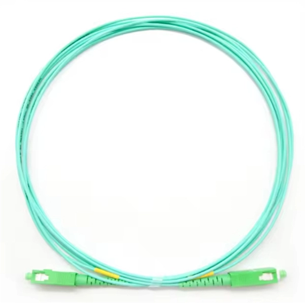
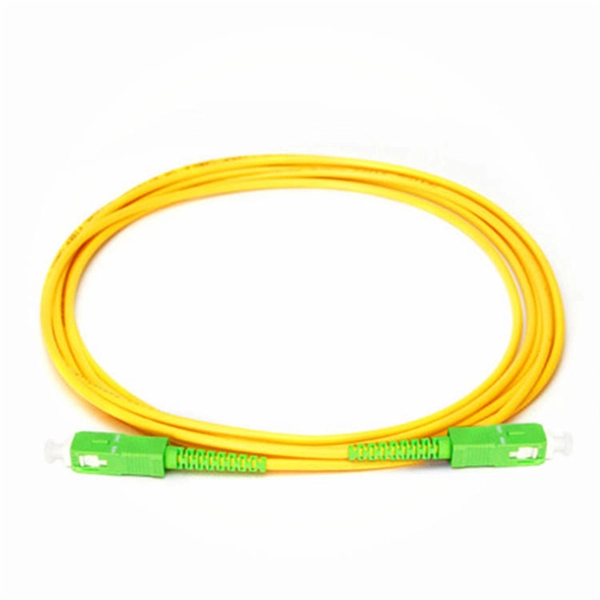
Fiber optic transmission distance varies based on fiber type, environmental conditions, and equipment selection. This guide explores the key factors affecting fiber optic transmission distance and provides practical selection guidelines for a stable and. Fiber optic cables use light to transmit data, while traditional cables, such as copper cables, use electrical signals. In fiber optic cables, data is transmitted as pulses of light that travel along a thin strand of glass or plastic fiber. The core of the fiber is made of a highly transparent. In fiber-optic communication, a single-mode optical fiber, also known as fundamental- or mono-mode, is an optical fiber designed to carry only a single mode of light - the transverse mode. Dispersion. In the complex landscape of fiber optic infrastructure, selecting the right cable type—single-mode (OS1/OS2) or multimode (OM1/OM2/OM3/OM4/OM5)—can define a network's speed, reach, and cost-effectiveness. They feature low attenuation benchmarks 2 and minimal dispersion. They use OS1 or OS2 OS1 or OS2 classifications to.
[PDF]