Line cards are field-replaceable units (FRUs) that you can install in the line card slots on the front of the switch chassis. Cisco ® Catalyst ® 9400 Series switches are Cisco's lead modular enterprise access switching platform and as part of the Catalyst 9000 family, are built to transform your network to handle a hybrid world where the workplace is anywhere, endpoints could be anything, and applications are hosted all. The Cisco® Digital Network Architecture (Cisco DNATM) with Software-Defined Access (SD-Access) is the most advanced network fabric to power customer business. Cisco DNA is an open and extensible, software-driven architecture that accelerates and simplifies your enterprise network operations. The. Get Advice: Live Chat | +1-626-655-0998 | Email Check D-Link Core Switch Line Cards price and buy one with best discount. Fast shipping and free tech support. Built upon the foundation of the Catalyst 9000, the Catalyst 9600 Series offers scale and security when always-on is a. If you are installing line cards released after Junos OS Release 14. 1, ensure that the Switch Fabric module (SF module) EX9200-SF2 is installed in the switch chassis.
[PDF]
Electricity is delivered at a frequency of either 50 or 60 Hz, depending on the region. It is delivered to domestic customers as. In some countries as in Europe a supply may be made available for larger properties. Seen with an, the domestic power supply in North America would look like a, oscillating between −170 volts and 170 volts, giving an effective voltage of 12.
[PDF]

At Keats Manufacturing, we appreciate the integral role our toolingplays within the electrical distribution industry. Our specialty is complex precision metal stamping, wire forming, and assembly. With our state-of-the-art stamping press and four-s. At Keats Manufacturing, we appreciate the integral role our toolingplays within the electrical distribution industry. Our specialty is complex precision metal stamping, wire forming, and assembly. With our state-of-the-art stamping press and four-slide equipment, we construct the best tooling in the industry, working with projects from development. Discussions around the electrical industry frequently focus on power generation, but those discussions leave out an equally important sector: the distribution and transmission of energy. Parts from various industries, such as circuit breakers, distribution boxes, switches and lines/transformers, come together to perform vital functions within the e. Our metal services are utilized in a variety of applications within the electrical distribution industry. Here are just a few areas to which we contribute:. We utilize a variety of materials to craft our tooling, including: 1. Aluminum 2. Brass 3. Copper 4. Phosphor bronze 5. Silver 6. Stainless steel. At Keats, we offer a variety of secondary services to meet our clients' needs including: 1. Assembly 2. Deburring 3. Degreasing 4. Plating.
[PDF]

Chile, in partnership with Google, is launching the Humboldt Cable System, the first fiber-optic submarine cable connecting South America with Asia and Oceania. As of 2025, the plan is to build a 14,800-kilometre (9,200 mi) cable from Valparaiso, Chile, to. The Humboldt Cable System is a 14810 km submarine cable connecting Chile, French Polynesia and Australia, with branches for the possible connection of other countries and territories. Stretching about 15,000 kilometers, it will connect Valparaiso, Chile, to Sydney, Australia, and then extend to Asia. Developed with H2. The company specializes in advanced fiber optic telecommunications and is dedicated to deploying fiber optic networks throughout Chile, enhancing broadband access for consumers and businesses. Their extensive ultra-broadband network, built to high industry standards, supports the digitalization. Google and the Chilean government have signed an agreement to install the Chile Submarine Humboldt Cable, a 14,800 km undersea fiber-optic line linking Valparaíso, Chile, with Sydney via French Polynesia. Slated for completion by 2027, it will be the first-ever direct South Pacific cable.
[PDF]

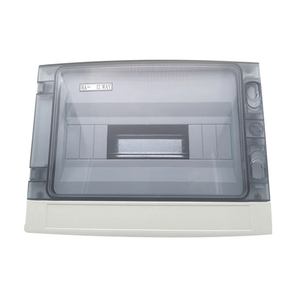
Primary: The main distribution panel, supplies power from the transformer. The terms primary, secondary, and tertiary distribution boxes are relative. Let's make an example for clarity: A newly constructed residential area introduces a 10kV power line to a substation. From the transformer's low-voltage side (0. Spot Networks are used for customers with the highest reliability requirements. This configuration connects two or more transformers (fed from at least two. A complete set of products can form a complete construction electricity three-level protection system, to achieve the purpose of one machine, one gate, one protection. The secondary box is designed with inside and outside doors and sprayed with plastic. Safe and beautiful, waterproof box top. These smaller breaker panels, also known as sub-distribution boards, are commonly used to provide power to secondary circuits within a building. Understanding the components and wiring configuration of an electrical sub panel is essential for safe and efficient electrical installations. In this. ACS takes the basic idea of zone wiring and combines it with pre-cut, pre-tested cable and plug-in connectors, to provide power and telecommunication systems that can be installed under raised floors (The Intelligent Floor), or in accessible ceilings (The Intelligent Ceiling). installed under.
[PDF]

Mainly 9steps: Step 1: cut cable with cutting machines in lengths Step 2: put the connector spare parts on the cable Step 3: Strip cable jacket, coating till bare fiber, and make all parts in ready Step 4: Insert fiber into ferrule, glue dispenser and heat oven Step 5:. Mainly 9steps: Step 1: cut cable with cutting machines in lengths Step 2: put the connector spare parts on the cable Step 3: Strip cable jacket, coating till bare fiber, and make all parts in ready Step 4: Insert fiber into ferrule, glue dispenser and heat oven Step 5:. Learn how to make a fiber optic patch cord step by step, from preparation to testing, for reliable high-performance connections. Most guides on making fiber optic patch cord 1 s feel incomplete. They often focus on the final assembly steps, leaving the foundational stages a mystery. From cable cutting to connector assembly and testing, you will gain valuable insights into the production of. Fiber optic patch cords and Pigtails are very important passive fiber optic components in fiber optic networks. Use the fiber optic cleaver to cut the. This document describes the installation and use of the mode-conditioning patch cords listed in Table 1. A mode-conditioning patch cord is shown in Figure 1 IEEE 802. 3z-compliant optical fiber assembly consisting of a single-mode fiber permanently coupled off-center to a 62. 5-micron multimode.
[PDF]
Mobility is a critical parameter influencing the overall performance of organic solar cells (OSCs). Herein, we innovatively elucidated the intricate interrelation between the photovoltaic molecular structures an.
[PDF]

Single fiber modules (BiDi) use one fiber for both transmitting and receiving data. This saves space and money. They are easier to set up and give steady communication. They use a thin fiber. Pioneer LX305 only has 1 optical input, can I add another with some kind of splitter? I love my new receiver but I need a second optical input and I'm wondering what my options are in this regard. Can anyone help? Thanks in advance. Edit: Everyone is going to ask this question, so here are my. The single-mode optical fiber is designed and engineered to carry one single light mode in a minimal core diameter. It is specified as the best for especially long-distance applications than multimode fiber. Due to its. The optical module serves as a crucial component in optical fiber communication systems, operating at the physical layer, which is the lowest layer in the OSI model. Its primary function is to achieve optoelectronic conversion by converting electrical signals into optical signals and vice versa. An. There are single-fiber and dual-fiber optical transceivers. How do we choose, and what are their differences and advantages? Let's learn about this! What is a Single-Fiber (BiDi) Transceiver? Single fiber module also called BiDi transceiver or WDM module.
[PDF]
Most residential and commercial electrical systems have at least one distribution box. A distribution box is a device that, as the name suggests, is designed to distribute electrical power. It takes the electrical.
[PDF]
⚡ In this video, you will see how to connect High Voltage Lines to an SDB Box step by step with real project photos and practical guidance. The entire work has been done following a proper engineering plan to ensure safety, durability, and professional quality. more In this video, I will. The primary side of the distribution transformer is supplied by two conductors known as a high-voltage line and a neutral respectively. The voltage between. ⚡ In this video, you will see step by step how to connect High Voltage Line to an LT Box with proper wiring methods and real project photos. Whether you're working on a renovation project, upgrading your home's electrical system, or simply learning more about electrical installations, this video wil. This guide is perfect for beginners and professionals who want to set up their high voltage equipment properly. more Learn how.
[PDF]

Search by part number or description such as CAT5, CAT6, OSP, etc. Sort by any of the table headers. Use the drop down menu to filter by product category and type. Sort by any. Welcome to the Corning LANscape® Solutions Product Drawings Resource Center, your complete source for our optical hardware component drawings. The two-dimensional and isometric hardware products drawings are available in PDF (Adobe® Acrobat®), DXF (AutoCAD®), VSS (Visio® Stencil) formats, and. Free CAD and BIM blocks library - content for AutoCAD, AutoCAD LT, Revit, Inventor, Fusion 360 and other 2D and 3D CAD applications by Autodesk. CAD blocks and files can be downloaded in the formats DWG, RFA, IPT, F3D. You can exchange useful blocks and symbols with other CAD and BIM users. When possible we have included both linear and nonlinear cable models for your use as appropriate. The use of a linear cable model may be acceptable for calculating loads and sags in an as-built situation such as joint use applications, or when linear elastic behavior and nominal creep are desired. The two linetypes are shown below. The appearance is similar but slightly different. Does anyone have such a code that they could share with me? I struggled for an hour or so and came up with this. There is a small gap on the left side of the circle.
[PDF]

Definition: Optical Line Terminal or optical line termination is a device that basically acts as a part of a passive optical network (PON). It is present in the central office of the network and manages the transmission and reception of information across the overall network. Optical line terminal. A GEPON system usually consists of an OLT (Optical Line Terminal) at the service provider's central office and multiple ONU (Optical Network Units) or ONT (Optical Network Terminals) close to the end user as optical splitters. In addition, the transmission between OLT and ONU/ONT adopts an optical. An Optical Line Terminal (OLT) is a fundamental element within optical communication networks, serving as a hub that facilitates the transmission and reception of data, voice, and video services to and from subscribers' locations. It acts as the central point for controlling and managing network. In optical fiber technology, one of the most widely used devices is an optical line terminal, also called OLT. It can transmit and receive data at several hundreds of kilometers without loss. The OLT is responsible for converting incoming optical signals into electrical signals, which are.
[PDF]
Search below to explore initial fiber availability in your area. Login to your CarrierFinder account for detailed insights and full access to carrier data. Enter your address and discover fiber and broadband internet providers. We'll show you which fiber networks and providers serve your address and the best plans. Fiber broadband, or fiber internet, is powered by fiber optic cables and has the potential to transmit data at much higher speeds than DSL or cable internet. How do I know if I have AT&T home internet availability at my address? AT&T home internet availability depends on your address. This means. By integrating Frontier's complementary pure-play fiber network with Verizon's industry-leading Fios and mobility assets, the company now has an expanded reach of almost 30 million fiber passings across 31 states and Washington, D. With the greater availability of premium home internet and. Fiber internet is a broadband connection that runs on light signals from fiber-optic cabling, delivering multi-gig upload and download speeds. It's the fastest and most reliable internet you can get, and most plans come with straightforward pricing and included Wi-Fi equipment. The map will be updated continuously to improve its accuracy through a combination of FCC verification efforts, new data from Internet.
[PDF]


