Find Prefabricated Telecom Shelter manufacturers, suppliers, dealers & latest prices from top companies in India. We are the first Indian company to provide 'Ready to Erect' Telecom Shelters in India with in-house Design, Engineering, Manufacturing and Erection / Installation capability all across India for efficient and cost effective operations of telecom equipment. (Dust Weather proof Insulated Cabin for. Prominent & Leading Manufacturer from Greater Noida, we offer portable prefabricated shelters and puf insulated telecom shelter. Our broad scope of pre-assembled covers incorporates a wide exhibit of Portable Telecom Shelters. Designed for rapid deployment and exceptional durability, our portable shelters are ideal for various applications, including the telecom and railway. Leading Manufacturer of prefabricated telecom shelters from Faridabad. Constructed with durable materials, these shelters ensure reliable performance.
[PDF]

This blog article entry considers the merits of choosing which of various low loss RF coaxial cables to use for IoT, LTE or LORA wireless applications where an external antenna is used to connect to router, gateway or terminal. The choice looks deceptively simple—pick a length, screw it on—but RF engineers know the truth: every extra meter quietly eats away at your link budget, especially once you cross 2 GHz. It's not just about length; the cable type, connector quality, and even mounting environment make a measurable. Audio generated by DropInBlog's Blog Voice AI™ may have slight pronunciation nuances. In this article, we will consider cables such as RG174, RG58, RF195. The cheap connectors have inferior dielectric between the poles as well as poorer grades of metal. The dielectric won't handle high power (KW range) as well and the center pin can more easily shift causing impedance problems if they are moved frequently. RF connectors are usually used with coaxial cables. They are designed to maintain the shielding that the coaxial design offers. The better and newer. Besides the wide range of RF connectors, Telegärtner also provides a considerable range of suitable coaxial low loss cables. Using this one-stop shopping option at Telegärtner makes your purchasing process even more efficient. The main use of low loss cables are all kinds of wireless applications.
[PDF]

Compare fiber optic and copper Ethernet cables across speed, distance, cost, installation difficulty, and use case metrics. Use the interactive scenario selector to find the right medium for your specific network — all processed locally in your browser. PoE Required?. The core difference between fiber optic and copper cables lies in how they carry data. One uses light, the other electricity—and that distinction shapes everything from speed to signal integrity. Fiber optics transmit data as pulses of light through ultra-thin strands of glass or silica. Both technologies can deliver high-speed connectivity, but they behave differently under real-world constraints such as. However, the exponential growth in data demand has positioned fiber optic technology as the superior alternative for performance, scalability, and future-readiness. This article provides a detailed technical comparison between fiber optic and copper cables, offering a clear perspective for. Fiber optic tends to be the more premium solution, while copper wiring is far more common, but why is that? What are the differences between these two cable types, and why might you want to pick one over the other? Here's everything you need to know about fiber vs. copper cables, to help you pick. Several factors are converging to drive the switch from copper to fiber – and cost is a big one. A recent investor presentation by AT&T claimed that fiber was 35% less costly to maintain than copper.
[PDF]

Insertion loss tells you how much weaker the signal becomes after passing through the splitter. Let's say you have a laser output at 0 dBm (which is 1 milliwatt of optical power). If you use a 1×8 splitter with ~10. 5 dB of insertion loss, the power at each output would be: 0 dBm – 10. 5. Enter excess loss from the splitter datasheet for your wavelength. Add connector and splice quantities with realistic planning losses. Include any additional component losses and an engineering margin. Enable power budget to estimate received power and margin. Press Calculate to show results above. Understanding optical splitter loss isn't just about plugging numbers into a calculator. It's about knowing what factors contribute to that loss, how manufacturers specify it, and how it impacts the overall performance and reach of your network. Ignore it, and you might find your signal too weak to. Optical insertion loss refers to the signal loss resulting from the insertion of components such as connectors or splices in an optical fiber system. Common ratios: For cascades, add losses and validate margin using the Optical Budget tool. This Fiber Optic Splitter Insertion Loss is the splitter devices loss, Considering fiber connectors or connectors+adapter insertion loss in LGX, The fiber splitter IL would be a little bigger. To make clear the basic ftth fiber splitter loss in performance, You can refer to the below loss chart.
[PDF]

In this study we consider a basic mechanism for the conversion from Sol. Energy to power generation and the progress in PV development by using silicon materials. Modules based on c-Si cells account for more than 90% of the photovoltaic capacity installed worldwide, which is why the analysis in this paper focusses on this cell type. This study provides an overview of the current state of silicon-based photovoltaic technology, the direction of. The U. Department of Energy (DOE) Solar Energy Technologies Office (SETO) supports crystalline silicon photovoltaic (PV) research and development efforts that lead to market-ready technologies. 7 × 10 17 W of Sol. Energy irradiates the Earth, which is more than 10,000 times the global energy consumption [6, 7]. Conventional PV cells are made from a silicon wafer that transforms sunlight directly into electricity. These silicon-based solar cells use 150 to 200. Crystalline silicon (c-Si) photovoltaics has long been considered energy intensive and costly. Over the past decades, spectacular improvements along the manufacturing chain have made c-Si a low-cost source of electricity that cannot be ignored anymore. Over 125 GW of c-Si modules have been.
[PDF]
HDPE Silicon Core Pipe is a high-performance conduit specially designed for optical cable protection. Featuring a durable HDPE outer layer and a low-friction silicon inner lining, it enables smooth and long-distance cable installation in telecom, internet, and infrastructure projects. In this. Qitian Communication Industry Ningxia Co., Ltd is a well-known supplier of communication pipeline and related supporting products., was established in 2006. Over the years, we have been dedicated to providing solutions for high-speed. Home / Library / Public Doc / Product Specification Sheets NEED A CUSTOM QUOTE? Work with our experts to build the best solution for your environment. Email us using the Request a Quote below, or. Established in 2007, the 50,000sqm Jiajie Manufacturing Base owns the most advanced automatic production lines in China to reach volume production capacity up to 60tons/month, ranking the frontline in the world. One-stop Service / Your satisfaction, our motivation. Material: PE 80, PE 100 2. Size: 32/26, 34/28, 40/33,46/38, 50/41, 63/54 3. CO (Certificate of Origin): China, CO could be provided by free. MOQ: Trial Order or 1*20ft containers by. Optical Fiber Core could be applied as G. A2, OM1, OM2, OM3, OM4 according to needs. Maximum Tensile Strength could be changed according to technical demand. Standard: TS EN 60794 +20 C -20 C +70 C +20 C -Number of cycles: 2 turns -Time per each step: 12 hrs.
[PDF]

Grating couplers are simply components of a photonic circuit that use diffraction to couple light into or out of a waveguide. By utilizing geometry and diffraction, fiber optic cables can be coupled to silicon chips at any location on the chip, instead of just the edges. How does it. An optical fiber grating is a small segment within an optical fiber altered to act as a selective filter for light. This treated area functions like a specialized mirror, reflecting a specific wavelength of light while allowing all other wavelengths to pass through. How does it work? Key to. coupling efficiency is substantially increased by adding a gold bottom mirror to the structures. The measured coupling effi cloButene (BCB) wafer bonding, gold mirror, grating couplers, in en the fiber and the waveguides on a chip causes high insertion losses and high packaging costs. Periodic index modulation can be permanently written in a waveguide by periodically modulating the doping concentration in the waveguide medium, for example, or it can be created by an. In this example, we will use the Inverse Design toolbox (lumopt) to design a silicon-on-insulator (SOI) grating coupler. Compared to other optimization methods such as particle swarm optimization (PSO), this optimization algorithm enables obtaining the best solution in just a few iterations. How does it work? Key to.
[PDF]

China is scaling domestic capabilities, with TeraHop*, Hisense, Accezlink, amongst others, shipping millions of modules to power AI interconnects. The global silicon photonics market is projected to reach $9. 2 billion by 2028, with a CAGR of 19. 4% from 2023 to 2028. Asia Pacific is expected to grow at a CAGR of 22. 1% from 2023 to 2028, driven by data center. The increasing adoption of cloud computing, artificial intelligence, and machine learning necessitates more efficient and scalable optical interconnects, where silicon photonics offers a compelling solution due to its cost-effectiveness, miniaturization, and CMOS compatibility. 4% CAGR during the forecast period (2025-2031). Silicon photonics is experiencing strong growth due to the increasing demand for high-speed data transmission in AI, cloud computing. Yole Group unveils its latest photonic market and technology analyses, Silicon Photonics 2025 and Co-Packaged Optics for Data Centers 2025, which explore how AI-driven demand is reshaping connectivity, from transceivers to packaging innovation. 200G/channel will become the new mainstream, enabling. GlobalFoundries (GF) reported fourth-quarter 2025 revenue of $1. 83 billion and highlighted silicon photonics, advanced packaging, and GaN power as central growth engines tied to AI data center buildouts. Communications infrastructure and data center revenue rose 32% year-over-year in Q4 and 29% for.
[PDF]

Where traditional computer chips push electrons through copper wires, silicon photonic chips guide photons (particles of light) through tiny channels called waveguides etched into the same silicon material. The result is faster data transfer, less heat, and dramatically lower. Silicon photonics is a technology that uses light instead of electrical signals to move data through circuits built on silicon chips. The silicon is usually patterned with sub-micrometre precision, into microphotonic components. These operate in the infrared, most commonly at the 1. More simply, while traditional semiconductors like CPUs, GPUs, and SoCs in computers and smartphones are silicon-based integrated circuits, silicon. Silicon photonics is a type of integrated photonics that utilizes silicon-based fabrication processes to create optical chips. Thereby it opens a route towards very advanced PICs with very high yield and low cost. More precisely, silicon photonics. Photonic crystals with extremely high quality cavities. Waveguide losses dominated by scattering. Use better litho + etch CROSSINGS. Optional undercut to lower thermal leakage. ELECTRO-OPTIC EFFECT IN SILICON: INJECTION VS.
[PDF]
Over the past few decades, silicon-based solar cells have been used in the photovoltaic (PV) industry because of the abundance of silicon material and the mature fabrication process. Department of Energy (DOE) Solar Energy Technologies Office (SETO) supports crystalline silicon photovoltaic (PV) research and development efforts that lead to market-ready technologies. Below is a summary of how a silicon solar module is made, recent advances in cell design, and the. Silicon solar cells are the dominant technology in the global renewable energy transition, accounting for over 95% of the photovoltaic (PV) market share. Decades of engineering refinement have transformed this once expensive space technology into the most cost-effective source of new electricity. Photovoltaic (PV) installations have experienced significant growth in the past 20 years. During this period, the solar industry has witnessed technological advances, cost reductions, and increased awareness of renewable energy's benefits. Research activities at ISFH in the field of silicon. In the topic "Silicon Solar Cells and Modules", we support silicon photovoltaics along the entire value chain with the aim of bringing sustainable, efficient and cost-effective solar cells and modules to industrial maturity. However, as more electrical devices with wearable and portable functions are required, silicon-based PV solar cells.
[PDF]

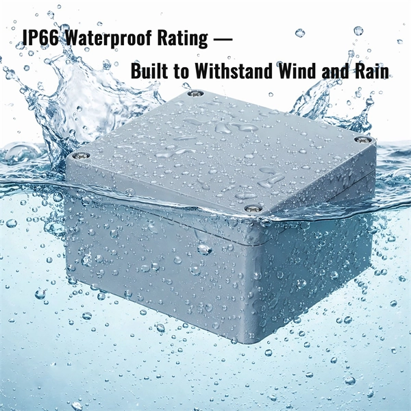
This article will compare waterproof connectors and non-waterproof connectors, highlighting their key differences, advantages, and best use cases in FTTH deployments. 🔍 What Are Waterproof Connectors?. In modern fiber optic deployments, one of the biggest challenges is ensuring stable and long-term connectivity in harsh outdoor environments. The comparison is typically triggered during outdoor deployments, edge network extensions, or hybrid indoor–outdoor transitions where connectors may be exposed. This is where Ruggedized Fiber Optic Connectors come in. Whether you are connecting a Remote Radio Unit (RRU) for Ericsson, Nokia, or Huawei, or setting up a harsh-environment sensing network, choosing the right waterproof interface is critical to preventing signal loss and network downtime. In. In today's fast-paced digital world, the choice of fiber optic connectors can significantly impact performance, reliability, and longevity of networking solutions. Among the varieties available on the market, waterproof fiber optic connectors have emerged as a superior option for many applications. In this blog, we will focus on comparing the performance of Mini LC.
[PDF]

The price of FRP trays can range from $10 to $50 per meter, depending on the specifications such as size, design, and environmental factors. Cable trays are vital in electrical installations, providing secure pathways for power, communication, and control cables across residential, commercial, and. Using 3/4" conduit for each cable at. 34/ft using 20 ft sections in tray and 10 ft sections for the drop. 21/ea for every 6 ft of cable for the drops and conduit couplers at. Understanding the key factors that influence their pricing helps engineers, contractors, and. This guide covers the critical steps, from selecting the right electrical cable tray and performing accurate cable fill calculations to managing a safe cable pull through and ensuring all bonding and grounding requirements are met. For licensed electricians, mastering these principles is essential. Market context (at-a-glance): Industry analysts valued the global low voltage wire & cable market at roughly USD ~ 145. 7 billion in 2024 and is projected to grow at a CAGR of 7. 2% from 2025 through 2034. Nearly 70% of new homes are now built with low voltage systems (industry estimate) meaning that. Ladder type cable trays are built for heavy-duty routing. In power-heavy areas, they prevent failures that would be far more expensive than the tray itself. Perforated cable trays sit in the middle. They cost less than ladder.
[PDF]

Link your beam span to cell B2 and sweep values from 3m to 12m. Reactions, moments, and deflections update live in your worksheet — no re-entering anything. Chain results into downstream calcs like connection design or foundation sizing, all inside one workbook. Reactions, SFD, BMD, deflections — all live. Change a cell, everything updates. Results write back to wherever you need them. Not a toy calculator. Your loads come from cells. Change a value in Excel — the. The first step in creating your beam calculator is setting up the input sections of the spreadsheet. You'll want to start with a section for basic inputs, including the system of units (inch or metric), the length of the beam, Young's modulus, and the area moment of inertia. This setup ensures that. A free VBA library to make structural analysis easy in Microsoft Excel. In this post, we will build a tool to analyze a Simply Supported Beam subjected to a single Point Load. Features static and moving loads, support settlements, non-linear analysys of beam on elastic foundation and influence lines analysis. It allows elastic and column support conditions, hinges and variable beam. "BEAMANAL. xls" is a MS-Excel spreadsheet workbook for the analysis of single-span beams (simple, propped, fixed, or cantilever) and continuous beams of up to 5 spans. The user may apply point, uniform, and varying loads, as well as applied moments.
[PDF]
