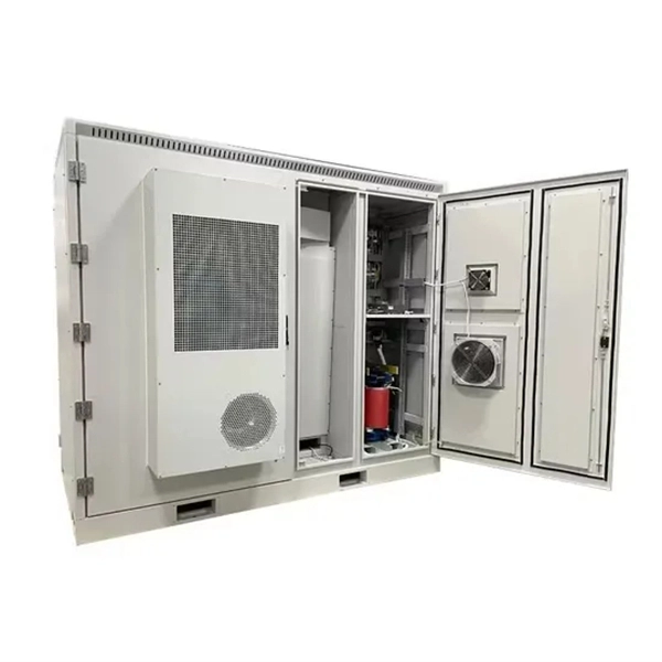
For busbar sizing, the primary references are IEC 61439 (for low-voltage switchgear and controlgear assemblies) and IEC 60287 (for current-carrying capacity of cables). IEC 61439 is a standard developed by the International Electrotechnical Commission (IEC) that covers design verification for low-voltage electrical products and assemblies. The IEC 61439. With SIRIUS, SENTRON, SIVACON and ALPHA, we offer an innovative portfolio for standard-compliant and demand-oriented applications. Efficient engineering tools and innovative cloud-based solutions can be flexibly tailored to individual requirements. com/system-certificates/ep). The. 7 cycles of 24 h each to salt mist test according to IEC 60068-2-11; (Test Ka: Salt mist), at a temperature of (35 ± 2) °C. The test shall be carried out according to IEC 60068-2-2 Test Bb, at a temperature of 70 °C, with natural air circulation, for a duration of 168 h (7 days) and with a recovery. The International Electrotechnical Commission (IEC) issues globally accepted standards that promote safety and efficiency in electrical engineering. Standard sizes and ratings and a complete line of components allow each system to be tailored to suit the requirements of each application, while at the same time provide the.
[PDF]

Porsche is improving the digital experience for the model year 2026 911, Taycan, Panamera and Cayenne model series. The revised Porsche Communication Management (PCM) system features more performance and offers access to the Porsche App Center. Communication Power System by Application (Wireless Access Network Base Station, Renewable Energy System, Internet Data Center, Core Network Center Room, Others), by Types (DC Power Supply, AC Power Supply), by North America (United States, Canada, Mexico), by South America (Brazil, Argentina, Rest. Tokyo – January 23, 2026 – NEC Corporation (NEC; TSE: 6701) today announced the development of a new Radio Unit (RU) for 5G Sub-6GHz band base stations, featuring Massive MIMO (*1) technology. You can find EDB at www. CPI is looking for passionate individuals to help shape the future through innovation and discovery. Job Opportunities » © 2026. In 2026, one theme is becoming increasingly clear: wireless power is evolving from a convenience feature into a foundational infrastructure layer for connected devices. What began as a wireless charging alternative is now shaping device architecture, user experience, and ecosystem design across.
[PDF]
Learn about the market conditions, opportunities, regulations, and business conditions in paraguay, prepared by at U. Embassies worldwide by Commerce Department, State Department and other U. agencies' professionals The standards regime in Paraguay includes obligatory and voluntary standards. The Group's environmental commitment is centred on 3 guiding lines: taking on board environmental management in the running of its industrial sites, reducing the environmental impact of its products by eco-design, providing environmentally friendly solutions that contribute to energy savings. Type. REV.
[PDF]

Perform a dielectric strength test to check the insulation properties of the busbars under high voltage conditions. The Partial Discharge test is crucial for determining long-term part. A busbar protection must be capable of clearing all phase-to-earth faults, and in the case where they can occur, phase-to-phase faults. Policy regarding fault clearance times required from busbar protection varies from utility to utility. Due to the fact that the short-circuit levels of bus bars. Early detection of cracks is crucial for preventing. Check the mechanical. The voltage of the faulted phase decreases (in case of incomplete grounding) or drops to zero (in case of solid grounding). In stable grounding, the. Busbar Differential Protection Definition: Busbar differential protection is a scheme that quickly isolates faults by comparing currents entering and leaving the busbar using Kirchoff's current law. Current Differential Protection: This protection method connects CT secondaries in parallel and. That's based on air insulated buswork well above your head and a reasonable set of remote zone 2 times. I agree with you as chances of surviving a bus fault is practically non existent at 110/220kV regardless if its cleared in ~100ms via busbar prot scheme or via remote end in zone 2 times of.
[PDF]

This guide explains what a fiber optic termination box is, how it works in practice, where it is typically installed, and how to choose the right model for different network environments. What Is a Fiber Optic Termination Box?. A Fiber Termination Box, also known as a Fiber Distribution Box, is a crucial component in fiber optic networks. It serves as a termination point for optical fibers, providing a secure and organized space for connecting and managing fiber optic cables. It functions as a junction between the incoming fiber cable and the outgoing customer-side fiber cable, where one fiber can be spliced, patched. A fiber optic termination box is a core component in modern fiber optic networks, providing a secure and organized point for fiber termination, splicing, and distribution. It is widely deployed in FTTH, FTTB, and other access networks to ensure stable signal transmission from backbone cables to end. Fiber termination box (FTB), also known as optical terminal box (OTB), generally refers to a distribution box specially designed for fiber cable management (fiber patch cables/pigtails) in FTTH applications. To ensure consistent performance and longevity, it is essential to adhere to strict technical specifications.
[PDF]

Check for proper IP/NEMA ratings and material quality. Ensure safe placement: install in dry, accessible areas with good ventilation and at appropriate height (typically ~1. Practice good wiring: secure grounding, neat cable management, proper insulation, and correct wire gauge and. In this guide, we'll break down everything you need to know to install a distribution box correctly and confidently. Choose the right box based on environment (indoor/outdoor), load capacity, and durability. It is usually equipped with circuit breakers, fuses, terminal connectors, and other components. It is mainly used to isolate fault circuits, prevent overload, and ensure the safe operation of. Think of your home's distribution box as the Grand Central Station of your electrical system. Just like travelers need clear pathways and safety protocols, your electrical circuits need proper management to prevent chaos. The National Electrical Code (NEC) requirements might seem like bureaucratic. The ideal location to install electrical distribution boxes should keep a distance from water, flammable and explosive substances and corrosive substances. If they need to be placed outdoors, especially in high humidity, you must ensure their waterproofness. And all the switching and protective devices are installed in the distribution box. Single Phase Distribution Box generally consists of Double Pole MCBs, Single Pole MCBs, and RCCBs.
[PDF]

This document provides specifications for various distribution boxes including dimensions, mounting sizes, and number of ways. It stipulates requirements for enclosure materials, installation dimensions, the mandatory "one equipment, one switch, one RCD" rule, mechanical structure, earthing systems. RB21 is a portable, safe, economic and easy to use pre-wired low voltage ready board with 2 (Two) sockets, 1 (One) lighting lamp and protection area. It has 4 (Four) mounting lugs suitable for wall installation and additional knockout for future use. It is suitable for residential (small holding. The World Bank is financing the National Electrification Analysis (NEA) on behalf of the GoA for which NRECA International (NRECA) was contracted in September 2019. The NEA project is designed to perform a geospatial evaluation of electrification access options to achieve GoA access goals by. This guide walks you through everything about electrical enclosure box sizes — from measurement standards and IP ratings to sizing formulas and common pitfalls. Before talking numbers, let's clarify what “size” really means. Dimensions included are length, width. IEC 62262 IK10.
[PDF]

All meter and service equipment installations shall comply with the service requirements of CRA-ES and with rules and regulations of the inspection authorities having jurisdiction. All meter sockets and enclosures shall be listed and approved by a recognized testing lab. If any question arises for. Added dual meter for ethernet over IP without breakout block. Updated standard includes newer design that no longer requires breakout block and cellular data update. Note for window clearance added on page 6. Current. This informational booklet is issued by American Electric Power Company for the guidance of Customers, Engineers, Architects, Contractors and other interested parties planning electrical installations for residential buildings and small commercial establishments. The information and recommendations. Submit Service Request forms describing the proposed electrical installation and expected loads. Include the existing service designation and meter location for rewires or upgrades to the existing service. For residential. The DTE Electric Planner will determine the location of the building service and the meter equipment. Choose the right box based on environment (indoor/outdoor), load capacity, and durability. Check for proper IP/NEMA ratings and material quality. Ensure safe placement: install in.
[PDF]
This document outlines the key requirements for cable tray layout, installation, and fireproofing in industrial and commercial environments. Route Planning and Layout Principles. Provides technical requirements concerning the construction, testing, and performance of metal cable tray systems. It is the first joint effort of NEMA and CSA International to put in one place standards for metal trays per both NEMA and CSA methods. Addresses shipping. Method Statement installation of Cable Trays and Ladders - Planning Engineer FZE. Whether you're designing a new. Below is the detailed cable tray installation method statement not only for cable tray but also applicable for GI ladder and trunking for indoor and outdoor applications and in service rooms like pump rooms, electrical rooms and plant rooms etc. All materials intended for cable tray, ladder and. Cable tray installation must comply with specific technical standards to ensure electrical safety, system reliability, and long-term maintainability. The mechanical and electrical characteristics, tests, certifications, overall quality management, recommendations mentioned in this technical guide only apply to our own cable management ranges and cannot under any circumstances be transpos regulations which.
[PDF]

Compare fiber optic and copper Ethernet cables across speed, distance, cost, installation difficulty, and use case metrics. Use the interactive scenario selector to find the right medium for your specific network — all processed locally in your browser. PoE Required?. The core difference between fiber optic and copper cables lies in how they carry data. One uses light, the other electricity—and that distinction shapes everything from speed to signal integrity. Fiber optics transmit data as pulses of light through ultra-thin strands of glass or silica. Both technologies can deliver high-speed connectivity, but they behave differently under real-world constraints such as. However, the exponential growth in data demand has positioned fiber optic technology as the superior alternative for performance, scalability, and future-readiness. This article provides a detailed technical comparison between fiber optic and copper cables, offering a clear perspective for. Fiber optic tends to be the more premium solution, while copper wiring is far more common, but why is that? What are the differences between these two cable types, and why might you want to pick one over the other? Here's everything you need to know about fiber vs. copper cables, to help you pick. Several factors are converging to drive the switch from copper to fiber – and cost is a big one. A recent investor presentation by AT&T claimed that fiber was 35% less costly to maintain than copper.
[PDF]
Find Prefabricated Telecom Shelter manufacturers, suppliers, dealers & latest prices from top companies in India. We are the first Indian company to provide 'Ready to Erect' Telecom Shelters in India with in-house Design, Engineering, Manufacturing and Erection / Installation capability all across India for efficient and cost effective operations of telecom equipment. (Dust Weather proof Insulated Cabin for. Prominent & Leading Manufacturer from Greater Noida, we offer portable prefabricated shelters and puf insulated telecom shelter. Our broad scope of pre-assembled covers incorporates a wide exhibit of Portable Telecom Shelters. Designed for rapid deployment and exceptional durability, our portable shelters are ideal for various applications, including the telecom and railway. Leading Manufacturer of prefabricated telecom shelters from Faridabad. Constructed with durable materials, these shelters ensure reliable performance.
[PDF]

This blog article entry considers the merits of choosing which of various low loss RF coaxial cables to use for IoT, LTE or LORA wireless applications where an external antenna is used to connect to router, gateway or terminal. The choice looks deceptively simple—pick a length, screw it on—but RF engineers know the truth: every extra meter quietly eats away at your link budget, especially once you cross 2 GHz. It's not just about length; the cable type, connector quality, and even mounting environment make a measurable. Audio generated by DropInBlog's Blog Voice AI™ may have slight pronunciation nuances. In this article, we will consider cables such as RG174, RG58, RF195. The cheap connectors have inferior dielectric between the poles as well as poorer grades of metal. The dielectric won't handle high power (KW range) as well and the center pin can more easily shift causing impedance problems if they are moved frequently. RF connectors are usually used with coaxial cables. They are designed to maintain the shielding that the coaxial design offers. The better and newer. Besides the wide range of RF connectors, Telegärtner also provides a considerable range of suitable coaxial low loss cables. Using this one-stop shopping option at Telegärtner makes your purchasing process even more efficient. The main use of low loss cables are all kinds of wireless applications.
[PDF]

Check the diagnostic information, which shows that the received optical power is low, with a threshold of -3 to -23. 01, currently at -22. Once it exceeds the threshold, an alarm will be triggered. Troubleshoot the link, and if the link is normal, replace the optical module. The receive power of an optical module is too low. Indicates the MIB object ID of the alarm. The device management or driver software has a bug. Use an optical power meter to check whether the transmit optical power of the optical module is normal. Remove and. When an optical module is running on a switch, it is often necessary to read its internal information to check the operating status, including link status, real-time Tx/Rx optical power, and temperature. Verifying module identification also helps confirm coding compatibility between the module and. The optical module on the port generates an alarm. Built into modern SFP/SFP+/ SFP28 /QSFP family modules and standardized by SFF-8472, DDM/DOM exposes real-time values for the module's temperature, supply. This chapter gives a description, severity, and troubleshooting procedure for each commonly encountered Cisco NCS 1001 alarm and condition. When an alarm is raised, refer to its clearing procedure. Default Severity: Critical (CR), Service Affecting (SA) Logical Object: EQUIPMENT The 0/PM [0|1] Unit.
[PDF]