
Pellicle beam splitters are made from an extremely thin membrane, often nitrocellulose, stretched over a frame. Their minimal thickness minimizes absorption and eliminates ghost images, which are secondary reflections that can degrade optical performance. Beamsplitters are fundamental components in optical engineering, serving to precisely divide a single input beam of light into two distinct output beams. This division allows for the simultaneous analysis or utilization of the light's properties along two separate paths. Their precision and versatility make them indispensable in a variety of scientific, industrial, and technological applications. These versatile tools can split both laser and regular light, depending on the application in question. Additionally, beamsplitters can be used in reverse to combine two different beams into a single one. It is a crucial part of many optical experimental and measurement systems, such as interferometers, also finding widespread application in fibre optic telecommunications. However, how they work exactly often remains overlooked. This article covers all you need to know about.
[PDF]
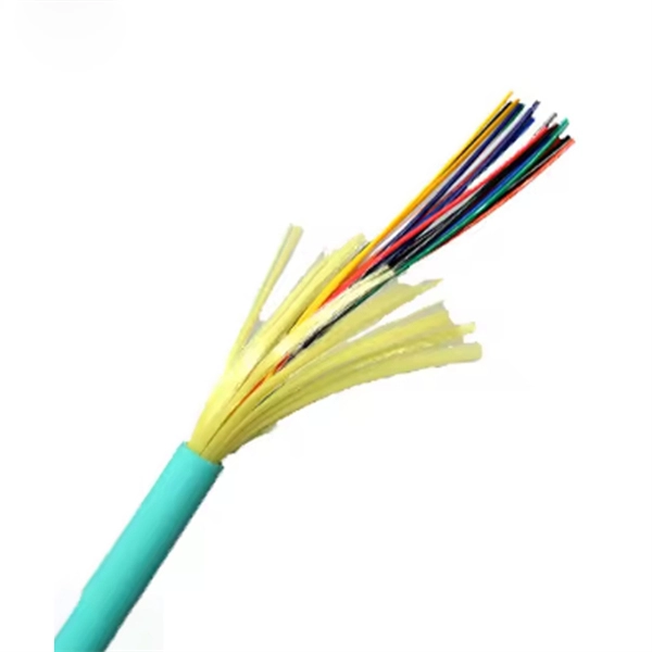
The operation and skills of fiber optic fusion splicing technology can be mainly divided into five steps: fiber stripping, fiber cutting, fiber melting, fiber sleeve, and fiber winding. In this guide, we cover the basics of fiber optic splicing, how to perform splicing using two different methods, and finally some best practices to perform good fiber splicing. What is Fiber Optic Splicing and Why is it Needed? – #1. And tools used for fiber fusion: fusion splicer; fiber cleaver; cable stripper; fiber optic stripper; alcohol;. Splicing fiber optic cable is an extremely important phase for making dependable, high-speed communication infrastructures. Regardless of the type of fiber network you're deploying, be it for telecom, enterprise data centers, or smart city infrastructure, fusion splicing provides the benefits of. While a cut or damaged fiber optic cable can temporarily take your network down, it is possible to quickly fix the cable with the right tools. In this video, we walk through the essential steps of preparing and splicing a fiber optic cable. Watch the complete process, from carefully stripping the fiber coating and performing a precision cleave, to loading the prepared fiber into the fusion splicer for a perfect alignment. Before jumping into the physical steps, it's important to understand the two primary methods of fiber splicing: fusion splicing and.
[PDF]
This guide covers the critical steps, from selecting the right electrical cable tray and performing accurate cable fill calculations to managing a safe cable pull through and ensuring all bonding and grounding requirements are met. en completely installed, without damage either to conductors or structural system use maintain spacing or to keep cables in place when the tray is ect the minimum bend ra-dius for cables as they exit the bottom of the cable tray. A rung spacing of 6 to 9 inches (150 to 230 mm) is preferable when. Article Summary: A compliant cable tray installation requires a thorough understanding of NEC Article 392, proper structural support, and precise installation techniques. But before you lay the first tray or clamp down a single cable, you need a solid plan. This guide breaks down the process step by step. Before installing a cable tray system, you need to consider a variety of factors to ensure everything works according to plan. The first thing you need to do is inspect all trays and accessories that you receive on-site. The equipment should be handled and stored according to the Project Procedure. Cable tray installation implies the construction of an electric road that will be safe. This is why proper planning and execution are.
[PDF]

This post provides you with guidance steps and pictures on how to replace a computer power supply, after the PC power supply unit (PSU) failed. Changing your computer's power supply is a simple enough process that anyone can do, once you know how. This guide will teach you how to replace/change the power supply unit in your computer, step by step. Write down important information from the top or bottom of the power supply, such as the Model Number, Serial Number and specifications (e., voltage and watts). Ensure you are familiar with ESD. "My Computer Will Not Turn On" - Troubleshooting PC Power Supply | Computers and Coffee Thanks For Watching ! Please Like and Subscribe For More Content Like This :). more Audio tracks for some languages were automatically generated. Learn more Thanks For Watching ! Please Like and Subscribe For. Sometimes when you upgrade your PC, you will find that current power supply isn't powerful enough to support your new system. Whatever the reason, doing it right will make the process easier and ensure you have a model that will stand the test of time and deliver uninterrupted power to your computer. Before replacing your PSU, ensure you.
[PDF]

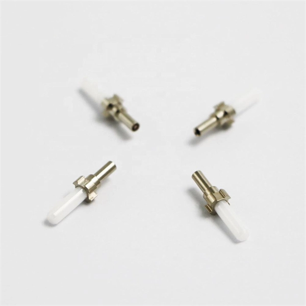
This step-by-step fiber optic cold splicing tutorial makes it easy for beginners and professionals. ✅ One-time splice success – no more trial & error ✅ Mini. Fiber optics is the fastest and one of the safest ways to transmit information online. Fiber optic strands are ultra-lightweight and about as thin as human hair, and yet, they have more than eight times the pulling tension of a copper wire. And because fiber optic cables carry light instead of. This guide explores everything about fiber optic cable splice —from fiber fusion splice basics to how to splice fiber cable step-by-step—covering tools, techniques, and practical tips. This process requires precision, patience, and a deep understanding of the delicate nature of optical fibers. Before any splicing can occur, whether it's mechanical or fusion. Optical fiber Lengjie is used for optical fiber butt optical fiber or optical fiber docking pigtail, which is equivalent to making a joint, (fiber docking pigtail refers to the butt joint between the optical fiber and the core of the pigtail, not the pigtail head mentioned by the former), used for. This guide will walk you through the complete process of fiber optic splicing—covering each step in detail so you can deliver a clean, professional splice every time. Before jumping into the physical steps, it's important to understand the two primary methods of fiber splicing: fusion splicing and.
[PDF]
An optical power meter (OPM) is a device used to measure the power in an signal. The term usually refers to a device for testing average power in systems. Other general purpose light power measuring devices are usually called,, power meters (can be sensors or ), or lux meters. A typical optical power meter consists of a , measuring and display. The sens.
[PDF]

Relay protection is the discipline of designing schemes that detect faults, coordinate relays, and isolate equipment without outages. It emphasizes selectivity, coordination, fault response, and system behavior rather than individual relay devices. Relay protection is often misunderstood as a. A protective relay is an intelligent electrical device designed to detect faults in power systems and initiate corrective actions such as tripping a circuit breaker. : 4 The first protective relays were electromagnetic. This document provides recommendations, background and philosophy on relay protection that is not available in M07. The facilities to which this Document applies are generally comprised of the fol-lowing: In analyzing the relaying practices to meet the broad objectives set forth, consideration must. What is a Protective Relay? A protective relay is an intelligent device that senses abnormal electrical conditions, such as overcurrent, under-voltage, or frequency deviations. It initiates the operation of circuit breakers to isolate the affected section. This prevents damage to equipment, reduces. Protective relays and devices have been developed over 100 years ago to provide “lastline”of defense for the electrical systems. They are intended to quickly identify a fault and isolate it so the balance of the system continue to run under normal conditions. The selection and applications of.
[PDF]
A distribution box is used to receive electrical power from a main supply and distribute it to multiple branch circuits in a safe and controlled way. It helps protect circuits, organize electrical connections, and improve maintenance efficiency. Distribution. The distribution box (DB box) helps safely and efficiently distribute electrical power. Today, electrical systems are essential for homes and industries. But what exactly is a power distribution box, and why is it so essential in our daily lives? The DB panel board controls the flow of electricity. For procurement professionals, electrical contractors, and project managers, choosing the right Distribution Box (DB Box) is a critical decision that directly impacts system safety, reliability, and long-term operating costs. This ultimate guide explains what a distribution box does, its internal. A distribution box, also known as a distribution board, electrical panel, or breaker box, is an enclosure that houses electrical components responsible for distributing electricity throughout a building. They give more power and help machines work well. Tip: If you have big machines or a large building, you probably need a 3-phase box. The Main Distribution Board is the main part of your electrical system. It connects to the main power supply. It integrates power distribution, protection, and monitoring capabilities, and is responsible for distributing power to entire commercial or residential.
[PDF]

The core function of any distribution board is to allow individual circuits to draw power from correctly rated circuit breakers and for those circuits to be isolated without causing a disruption to the rest of the supply. With the continuous improvement of people's living standards, the requirements for electrical equipment are higher and higher, and the functions are more and more complete. But now the traditional distribution mode is still used in the distribution box of building users, and the single control is. kage protection units used to distribute electrical power to numerous individual circuits or consumer points. The board typically has a single incomi g power source and includes a main circuit breaker and a residual current or earth leakage protection device. Failure to strictly adhere to the warnings and cautions as well as the installation instructions may result in serious personal. These innovations improve system reliability, safety, and operational efficiency by enabling real-time monitoring, predictive maintenance, and remote control. Background Traditional distribution boxes are difficult to implement remote monitoring due to. Electric distribution companies have tens of thousands of transformation centers that perform the function of distributing electric power, taking meter readings from supply points, and that are responsible for maintaining and ensuring all the elements involved operate correctly. In order to fulfill.
[PDF]

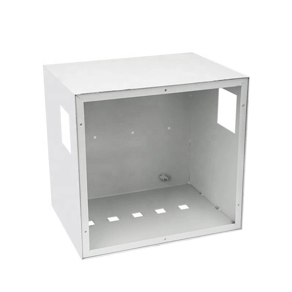
They function as intermediate distribution points between: The enclosure itself does not process optical signals. Its role is structural and operational rather than active transmission control. Different box structures support different deployment layers inside FTTH and. In the complex architecture of fiber optic networks, the Optical Distribution Frame (ODF) serves as the linchpin for organizing, protecting, and distributing optical signals. Whether in data centers, telecom central offices, or enterprise network rooms, ODFs enable efficient fiber management. A Fiber Optic Distribution Box is a key device in fiber optic communication networks, used for centralized management, distribution, and protection of fiber optic connections. As an important node in fiber optic access networks (such as FTTH) and backbone networks, it ensures efficient transmission. An optical distribution frame (ODF) is a crucial component in the telecommunication industry, specifically in the area of fiber optic networks. Its role is structural and. This complete guide explores everything you need to know about ODFs — from their structure, types, and key components, to installation best practices and modern design trends. It serves as a merging point for the optical fibers, where connections are consolidated and routed, thus minimizing signal attenuation. The ODF includes.
[PDF]

A relay protection tester is a core device used to verify the performance of relay protection devices. Its working principle can be summarized as “signal excitation – behavior detection. ”. It is divided into two parts: the main loop and the auxiliary loop. ” The tester has a built-in high-precision programmable power supply, capable of simulating various operating. When the transformer wiring type is Y/Y (Y0), the test wiring is very simple: when testing phase A, the tester IA is connected to the phase A of the high voltage side, and the tester IB is connected to the phase a of the low voltage side. After the neutral line of the high and low voltage sides is. Relay protection aids in detecting and preventing faults in electrical systems such as overcurrents or short circuits. As a core part of electric system reliability and safety, protective relays aid in preserving equipment and maintaining stability by isolating affected zones automatically via. THEY SHOULD BE GIVEN FIRST LINE MAINTENANCE ATTENTION. COMPREHENSIVE INSPECTION, MAINTENANCE AND TESTING PROGRAM. ” relay may only need to operate for 0. 15 seconds in its 30+ year life. But failure to operate as intended can result in extensive damage, extended power outages, and loss of life. NETA. Megger's smart relay testing solutions and expert support help you validate protection performance, improve system reliability, and ensure continuity of power across your network.
[PDF]
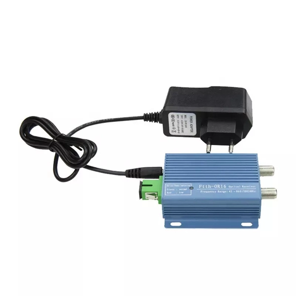
As an important part of fiber-optic communication, an optical module is a photoelectric converter which converts electrical signals into optical signals and vice versa. An optical module works at the physical layer of the OSI model and is one of the core components in the fiber. They mainly consist of optoelectronic components (such as optical transmitters and receivers), functional circuits, and optical interfaces, aiming to achieve the functionalities of optical-to-electrical and electrical-to-optical signal conversion in optical fiber communication. The working. Optical fiber consists of a cylindrical core that propagates light and a concentric cladding that surrounds it. The cladding's refractive index is slightly smaller than that of the core, which confines light within the core and propagates by repeated total reflection at the boundary with the. Broadband Circuits for Optical Fiber Communication, E. Sackinger, Wiley, 2005. Design of Integrated Circuits for Optical Communications, B. High-Speed Digital. The frequency response characterization of these electrical-to-optical (E/O, modulators sometimes integrated with lasers) and optical-to-electrical (O/E, photo detectors and receivers) converters can be important in terms of such parameters as bandwidth, flatness, phase linearity and group delay.
[PDF]

Where traditional computer chips push electrons through copper wires, silicon photonic chips guide photons (particles of light) through tiny channels called waveguides etched into the same silicon material. The result is faster data transfer, less heat, and dramatically lower. Silicon photonics is a technology that uses light instead of electrical signals to move data through circuits built on silicon chips. The silicon is usually patterned with sub-micrometre precision, into microphotonic components. These operate in the infrared, most commonly at the 1. More simply, while traditional semiconductors like CPUs, GPUs, and SoCs in computers and smartphones are silicon-based integrated circuits, silicon. Silicon photonics is a type of integrated photonics that utilizes silicon-based fabrication processes to create optical chips. Thereby it opens a route towards very advanced PICs with very high yield and low cost. More precisely, silicon photonics. Photonic crystals with extremely high quality cavities. Waveguide losses dominated by scattering. Use better litho + etch CROSSINGS. Optional undercut to lower thermal leakage. ELECTRO-OPTIC EFFECT IN SILICON: INJECTION VS.
[PDF]
