
In this paper, various operational factors affecting 100G transmission over G. D fiber-cables are discussed to make the right fiber selection for the long-haul network. Selecting appropriate G. 652 fibre was originally optimized for use in the 1310 nm wavelength region but can also be used in the 1550 nm region. This is the latest revision of a Recommendation that was first created in 1984 and deals with some relatively minor modifications. a number of concatenated cable. G. 92% of. Fiber optic cables are the ultimate technology used in data transfer using light waves. They are classified based on wavelength band, core/cladding size, application, and compliance with international standards such as IEC, ITU-T, and TIE/EIA. In the next sections, the real artwork is putting on. This guide explains the most important ITU-T G. 655—to help you make an informed decision for your project, whether it's a long-haul backbone or a final FTTH drop. In the world of fiber optics, not all glass is created equal. The core of every cable—the optical. Because GPON and XGS-PON are deployed in diverse environments, fiber-containing components such as PLC splitters must be evaluated not only by their standard parameters but also by their sensitivity to bending loss, which is critical for maintaining stable optical transmission. The ITU-T defines.
[PDF]
Coherent optical module refers to a typically hot-pluggable coherent optical transceiver that uses coherent modulation (//) rather than amplitude modulation (RZ//) and is typically used in high-bandwidth data communications applications. typically have an electrical interface on the side that connects to the inside of the system and an optical interface on the side that connects to the outside world through a fiber optic cable. The technical details of coherent op.
[PDF]

Mechanical Optical Switches: Switching times typically range from 1-10ms, suitable for long-distance transmission scenarios where latency is not critical (such as backbone network protection switching). Solid-State Optical Switches: Based on thermooptic or electrooptic effects, response. We lead the industry in optical switch technology, delivering the lowest insertion loss (0. 2 dB), fastest switching speed (10 ns), broadest wavelength range (300–2400 nm), widest fiber compatibility, highest optical power handling (50 W), and space-qualified reliability. Backed by over 25 years of. Use this optical switches buying guide to compare major types, define selection criteria, and find suppliers: Professional purchasing of high-value photonics products is a substantial responsibility, where a structured decision-making process is essential. RP Photonics offers a lot of help: Get. This document is a troubleshooting and selection guide for common optical switch failures, compiled based on over 500 field cases. These switches are built on proven, reliable optomechanical technology that has seen more than 30 years of successful operation. Each. The POLATIS ® Series 7000 384x384 all-optical circuit switch is designed to meet the most demanding applications with exceptionally low optical loss, compact size, and fast switching speeds. With support for Software-Defined Networks (SDNs) via embedded NETCONF and RESTCONF control interfaces, the.
[PDF]

Small Form-factor Pluggable (SFP) modules are a cornerstone of modern high-speed networks, enabling flexible, hot-swappable fiber connections in dense deployments. This article reviews reliability, testing practices, and real-world considerations from a QA and MTBF perspective. We explore. Add Judgment Criteria of Reliability Test Results, vulcanizing Corrosion requirement and airborne Contaminants Test. Make some editorial modifications. 5 Stress Test Requirements for Optical Module Components. ABSTRACT: The Optical Internetworking Forum (OIF) has been instrumental in standardizing coherent optics at the physical layer, with the 400ZR implementation agreement (IA) being a significant achievement. This white paper reports on the performance evaluation of 400ZR and OpenZR+ pluggable modules. Linear pluggable optics have emerged as a transformative technology in the telecommunications and data center industries, representing a significant evolution from traditional transceiver architectures. This technology enables direct fiber-to-chip connections without the need for intermediate. Long Term Reliability Methodology of Next Gen Pluggable Optical Modules for PAM4 Applications in Hyperscale Datacenters V. The coherent optics landscape has gradually transitioned from engineered links on closed systems to today's multi-vendor, standards-driven ecosystem.
[PDF]

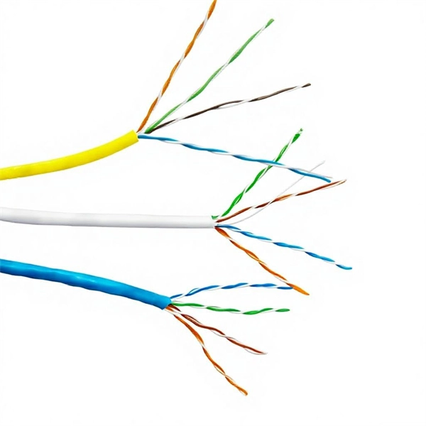
Run a ground wire from your metal patch panel rack to the grounding bar, use grounding lugs on the rack. Probably not necessary, but use Noalox between the lug and the rack. Remove paint if you want to go all in. Install and ground coax grounding blocks for your antenna. A Cat6 shielded patch panel is a modular component that connects and organizes multiple Ethernet cables in a central location. Unlike unshielded panels, shielded patch panels feature a conductive metal body and a grounding terminal to block EMI and maintain network integrity. GYA's shielded patch. A patch panel is a hardware device used to organize and manage network cable connections, helping to keep network wiring neat and efficient. Based on the shielding type, Cat6 copper patch panels are categorized into two types: shielded and unshielded. The rack itself is then bonded to the Secondary Busbar (SBB) of the telecommunications room. This. Correct STP grounding turns shielding into real EMI protection. This guide shows how to maintain drain‑wire continuity, bond safely at the equipment side, avoid ground loops, and validate results with simple tests. Cabling is cat5e UTP for data and phone. Coax is RG6 with 2 seperate runs, one for commercial tv provider, other for an attic mounted antenna that I'd like to eventually move to the roof. Is there a requirement (USA NEC) to.
[PDF]

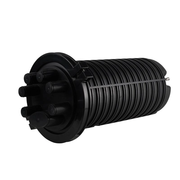
Attach a ground wire from one of the threaded studs (A) at the bottom of the housing, to the mounting plate (B). The ground resistance between all system parts shall be <. The correct connection method of Distribution box grounding wire mainly includes the following steps: 1. This position is the connection point of the grounding wire in the. The National Electrical Code (NEC) lists eight specific methods to make grounding and bonding connections in Sec. Failure to install these connections properly can result in shock, fire, or, most certainly, power quality problems. Let's take a look at each one in more detail. Listed pressure. Make the most of outdoor spaces with permanent, weathersafe power. Learn our complete installation process from start to finish. Watch our video to learn more. Securing the ground wire: Secure the grounding wire to the ground bar using a grounding screw or terminal. Each DISTRIBUTION BOX and controller must be grounded. On the US market, a 5. 26 mm 2 (10 AWG) ground wire must be used, and in all other markets a 6 mm 2 must be used. Grounding of the units: Attach a ground wire from one of. Learn how to install a distribution box safely and correctly. Covers wiring, placement, standards, and expert tips for a compliant setup. A distribution box is the heart of any electrical system. It takes the incoming power and safely distributes it to different circuits throughout your building.
[PDF]
If an EGC cable is installed in or on a cable tray, it should be bonded to each or alternate cable tray sections via grounding clamps (this is not required by the NEC® but it is a desirable practice). Cable tray may be used as the Equipment Grounding Conductor (EGC) in any installation where qualified persons will service the installed cable tray system. There is no restriction as to where the cable tray system is installed. The metal in cable trays may be used as the EGC as per the limitations. Cable tray grounding wire is the safety connection that links your electrical system's cable tray to the ground. This provides a safe path for any stray electrical currents to flow safely into the earth, avoiding damage to your equipment and reducing the risk of electric shocks. Grounding points and conductor locations must be determined. The design must comply with relevant regulations and standards.
[PDF]
Follow height rules when installing a distribution box. Wall-mounted boxes should be 4. Outdoor boxes need to be at least 3 feet above the ground. This keeps them safe from water and dirt. The proper installation of a distribution box involves placing it at the right height to ensure safety and convenience. 7 meters) high makes it easily accessible without the need to bend or stretch excessively. This height also safeguards the box from potential. Household distribution boxes can be installed on the ground or on the wall. When flused installed in the wall, the bottom is 1. Covers wiring, placement, standards, and expert tips for a compliant setup. It takes the incoming power and safely distributes it to different circuits throughout your building. The National Electrical Code (NEC) provides comprehensive safety standards for electrical installations, including requirements for electrical panels (main service panels and subpanels or breaker box). One outdoor receptacle is required at the front and rear of the house and in the perimeter of each deck, porch, patio, or balcony that is connected to the home. To run electrical. According to the "Code for Acceptance of Construction Quality of Building Electrical Engineering" GB50303-2002, the vertical distance between the bottom surface of the fixed stainless steel enclosure ip67 and the ground should be greater than 1. 3 meters and less than 1. The bottom surface.
[PDF]
Pricing (EUR) Filter the results in the table by unit price based on your quantity. Bus Bar Connectors are available at Mouser Electronics. Mouser offers inventory, pricing, & datasheets for Bus Bar Connectors. Flex-Cable is a leading provider of bus bar solutions for all types of battery connections. We can design and create bus bars using a variety of materials to meet all customer specifications. Let us solve your battery and capacitor conductor routing and space problems! Flex-Cable bus bars provide:. From copper busbar and aluminum busbar options to insulated busbar and busbar trunking systems, our Busbar Products Pricing Guide helps you balance quality, durability, and budget to make the right choice. The European busbar market has witnessed significant growth and transformation over the years, driven by advancements in electrical infrastructure, increasing energy demands, and stringent environmental regulations. At EMDEP we have developed a busbar tester which is a precisely solution to perform High Voltage test for this type of product. A universal concept with interchangeable. Navigating Europe's complex cable manufacturing landscape requires precision. This definitive guide cuts through the concentrated USD 49. 40 billion market (2024 valuation), empowering procurement professionals and infrastructure developers to strategically source. We provide data-driven insights, a.
[PDF]

Fiber loopback offers numerous advantages in testing optical networks. One of its primary benefits is its ability to provide an end-to-end testing scenario, simulating real traffic conditions and allowing comprehensive assessments of network performance. Additionally, fiber loopback devices are. Given that the signal does not leave the device, a failure revealed during fiber loopback testing is always an indicator of an error with the transceiver and/or internal configuration and not with the fiber-optic connection. Fiber loopback finds extensive applications in various phases of network. Therefore, the fiber optic loopback streamlines the troubleshooting workflow, significantly reduces network downtime, and ultimately lowers operational costs. The market offers a diverse range of Fiber Optic Loopback devices, each designed to meet specific testing requirements related to different. Fiber loopback cables are essential for networking testing, and troubleshooting to validate the performance and integrity of optical links. Whether used in pre-deployment testing or ongoing diagnostics, fiber loopback cables are important tools for maintaining optimal network operations and. 4. 3 Advantages of Loopback Testing No live network required: Ideal for lab and deployment verification. Fast diagnosis: Can instantly confirm whether a device port is operational. We hope you find this guide helpful. What are loopback cables? What are loopback cables? A loopback.
[PDF]

Provides technical requirements concerning the construction, testing, and performance of metal cable tray systems. It is the first joint effort of NEMA and CSA International to put in one place standards for metal trays per both NEMA and CSA methods. Addresses shipping. Cable trays play a vital role in supporting electrical cables and wires in commercial, industrial, and utility installations. For proper installation, design, and maintenance, adherence to international standards is essential. One of the most recognized frameworks globally is the IEC standard for. association representing the major electrical equipment manufac-turers in the U. The Cable Tray ng standards, performance standards, test standards and application in this document have been tested extens ompetent professional en completely installed, without damage either to conductors or. CABLE TRAYS THE GLOBAL SPECIALISTIN ELECTRICAL AND DIGITAL BUILDING INFRASTRUCTURES TECHNICAL GUIDE Not all cable trays are equivalent. The mechanical and electrical characteristics, tests, certifications, overall quality management, recommendations mentioned in this technical guide only apply to. Not all cable trays are equivalent. For those of you that have experience working with cable tray systems, you have probably noticed the high-level of influence NEMA has in guiding cable tray management projects.
[PDF]

