
These core components of optical fiber communication system — transmitter, optical fiber, receiver, plus supporting elements like amplifiers and multiplexers — enable lightning-fast, interference-free communication over vast distances. Fiber optic communication refers to a method of transmitting data that utilizes light instead of electrical signals to send information through optical fibers. It works on the principle of total internal reflection, allowing light to move through the fiber with very little loss. The process kicks. In order to comprehend how fiber optic applications work, it is important to understand the components of a fiber optic link. Simplistically, there are four main components in a fiber optic link (Figure 1). These systems rely on three vital components working together – the communication channel, the optical transmitter, and the optical receiver. Optical fiber communication system 1. Encoder Encoder converts the analog information like voice, figures, objects etc into the binary data. Optical fibers are thin, flexible strands of glass or plastic that serve as the medium for transmitting light signals. Some exceptional characteristic features of this type of communication system like large bandwidth, smaller diameter, lightweight, long-distance signal.
[PDF]
A fiber-optic cable, also known as an optical-fiber cable, is an assembly similar to an but containing one or more that are used to carry light. The optical fiber elements are typically individually coated with plastic layers and contained in a protective tube suitable for the environment where the cable is used. Different types of cable are used for in different applications, for exa.
[PDF]

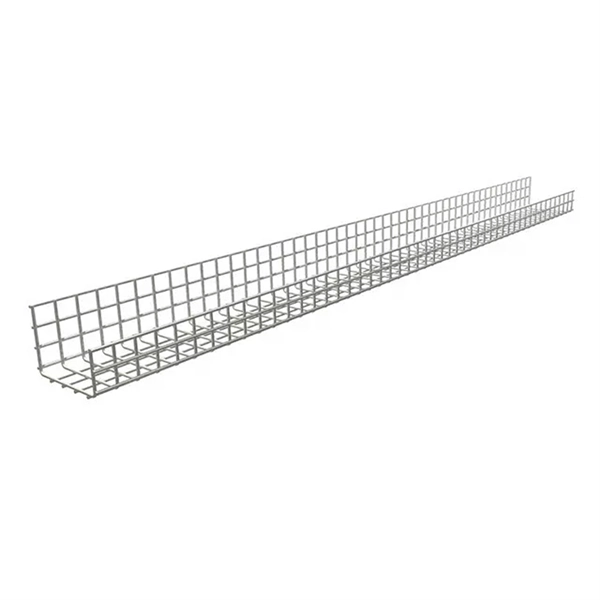
So, how do you connect multiple sections together? The answer: use the right connection accessories for a secure, aligned and continuous cable support system. In most cases, sections of wire mesh baskets or electrical cable trays are joined using couplers, bolts, or proprietary. Connecting cable trays correctly is essential for system safety, load stability, and long-term performance. The most common cable tray connection methods include: Each method differs in installation time, cost, flexibility, and strength. The Cable Ladder & Tray Components – Assembly Guide presents a comprehensive visual walkthrough of the assembly and installation process for cable ladder and tray systems. The images meticulously detail each component involved, including ladder sections, cross-members, splices, and tray segments. Make a 90 Gusset Bend in Cable Tray with Two Pieces Easy Way To Connect Pipes 17. Joining Cable Tray - Three Sytems Explained Explanation of the three systems available for joining cable tray, delivered by Greenmill Product Trainer, Simon Makin. ” What does this mean? Cable trays support cable the way that roadway bridges. After you have drafted cable tray or conduit runs, you can break an individual segment, break an entire run, or merge multiple segments. This can be helpful for determining the number of individual segments a manufacturer needs to supply. When merging segments, you cannot cross fittings to join.
[PDF]
Optical modules have a series of components inside, some of which have received attention from standards development organizations. In many cases, the baud rate of the optical interface does not equal the baud rate of the electrical interface. In these cases, a gearbox is used within the module to convert between the two rates. For example if the module supports 4 x 25 Gb/s electrical inputs and 2 wavelengths of 50 Gb/s optical inte.
[PDF]

They mainly consist of optoelectronic components (such as optical transmitters and receivers), functional circuits, and optical interfaces, aiming to achieve the functionalities of optical-to-electrical and electrical-to-optical signal conversion in optical fiber communication. As an essential component of optical fiber communication, optical modules are optoelectronic devices that facilitate the conversion between optical and electrical signals during the transmission process. Operating at the physical layer of the OSI model, optical modules are core devices in optical. Modern communication networks rely on optical transceivers to transfer data at the speed of light. Whether in 5G base stations, hyperscale data centers, or long-haul telecom networks, these modules convert electrical signals into optical ones — and back again — to ensure fast, stable, and. Optical modules are compact devices that convert electrical signals into optical signals and vice versa. They are used in fiber optic communication systems to transmit data over long distances with minimal loss and interference. These modules typically consist of a laser or LED transmitter, a. That is, metal medium communication represented by coaxial cables and network cables is gradually being replaced by optical fiber media.
[PDF]
Optical modules are essential components in modern communication networks, enabling high-speed data transmission over fiber optic cables. As the demand for faster and more reliable internet and data services grows, understanding these devices becomes increasingly important. Optical modules typically have an electrical interface on the side that connects to the inside of the system and an optical interface on the side that connects to the outside. That is, metal medium communication represented by coaxial cables and network cables is gradually being replaced by optical fiber media. Composition of Optical Modules The optical module, known as Optical Transceiver in. The optical module serves as a crucial component in optical fiber communication systems, operating at the physical layer, which is the lowest layer in the OSI model. Its primary function is to achieve optoelectronic conversion by converting electrical signals into optical signals and vice versa.
[PDF]
Typically, a beam splitter is made of a transparent substrate, such as glass or fused silica, with a thin, precisely engineered coating on its surface. Beamsplitters (also known as beam splitters or power splitters) are an optical component used to split an incident beam of light at a set ratio into a transmitted beam and a reflected beam. Beamsplitters are usually made as a reflective device that splits the beam into exactly 50/50 with half of. A fiber-optic splitter, also known as a beam splitter, is based on a quartz substrate of an integrated waveguide optical power distribution device, similar to a coaxial cable transmission system. The optical network system uses an optical signal coupled to the branch distribution. It is a crucial part of many optical experimental and measurement systems, such as interferometers, also finding widespread application in fibre optic telecommunications. Light from an input fiber is first collimated, then sent through a beam splitting optic to divide it into two. The resultant output beams are then focused back into the output fibers. Newport offers a wide variety of Beamsplitters in various shapes. Circular beamsplitters, plate beamsplitters and cube beamsplitters can be purchased for polarizing or non polarizing beamsplitting.
[PDF]
The features of a fiber termination box can significantly influence its price. Here are some key features to consider: 1. Splice Capacity:Higher capacity boxes will generally be more expensive, as they can accom.
[PDF]
This splice case protect fiber optic cables and juction from outside plant environment damage. They are made of reinforced ABS or PC plastic, which has high strength and corrosion resistance. In addition, the splice enclosures are all hermetically sealing structure, waterproof and. Standard polycarbonate (PC) or Glassfibre reinforced (PC+GLAS) PP ABS (Acrylnitrile-butadiene -styrene) Slightly lower UV resistance compared with PC. Recommended for outdoor use if protected against weather influences GRP – GLASS FIBRE REINFORCED POLYESTER Polycarbonate and ABS enclosure materials. The fiber optic splice closure is a closed structure used for splicing, protecting and managing optical fibers. Its material selection is crucial to ensure the quality and service life of the fiber optic splice closure. These boxes are well suited as optical cable splice collection points for DAS (Distributed Antenna Systems), MTU (Multi-Tenant Unit) commercial business applications, and MDU (Multi-Dwelling Unit). It is a reentry box which is made of PC or PP material. The shells and the base are sealed with silicone gum. This product can be re-entered and used again after it is opened. Typically selected for high-density OSP splicing and branching. What is the basic structure of Fiber Optic Splice Closure? The basic structure of Fiber Optic Splice Closure includes the box body, box components, sealing ring, and lock buckle.
[PDF]


