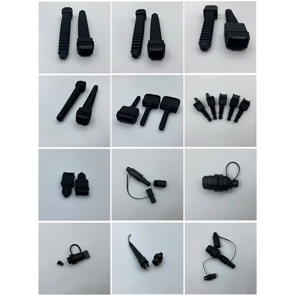
The FC/PC (Physical Contact) and FC/APC (Angled Physical Contact) fiber optic connectors are standardized under TIA EIA/TIA-604-4 and IEC 61754-13. ABSTRACT: This standard describes the point-to-point physical interface portions of Fibre Channel serial electrical and optical link variants that support the higher level Fibre Channel protocols includ-ing FC-FS, HIPPI, IPI, SCSI and others. This standard is recommended for new implementations but. Fiber connector types LC, SC, FC, ST, MTP, and MPO are widely used in past and present. What are the differences between them? Who is the most popular one? Find the answer in the article. What is a Fiber Connector? The optical fiber connector is a kind of detachable passive optical component used. An optical fiber connector is a device used to link optical fibers, facilitating the efficient transmission of light signals. An optical fiber connector enables quicker connection and disconnection than splicing. Unlike fiber splicing, which is permanent, connectors allow for easy connection and disconnection of cables, making them ideal for maintenance and flexibility in. Understanding fiber connector types—SC/APC, SC/PC, LC/UPC, LC/APC, ST/PC, FC/PC, and FC/APC—is essential for selecting the right interface for your application. Each type varies by shape, polish (APC, PC, or UPC), and return loss performance, which affect PC, UPC, and APC Polish Styles: What's the.
[PDF]

Bury cables from 12-36 inches (or 30-90 cm) deep. Where plant life, sidewalks, and other utilities already disrupt earth, it's safer to bury at as little as 24 inches or 60 cm, using protective conduits to limit the likelihood of damaged cables by inexperienced maintenance or. Bury cables from 12-36 inches (or 30-90 cm) deep. However, simply hitting this depth isn't enough to guarantee your network survives. Factors like the. Requirements vary based on location, cable type, and local regulations, with depths typically ranging from 18 to 48 inches. Residential areas require depths between 24 and 36 inches for most installations. This protects cables from landscaping activities and minor excavation work. This. The question of how deep to bury fiber optic cable has no single answer, as the required depth changes significantly based on location, environment, and specific application. Industry standards and regulations, such as those often referenced in the National Electrical Code (NEC), establish a. Fiber optic cables are typically buried between 12 and 36 inches (30–90 cm), depending on installation environment, soil conditions, and load requirements. In high-load areas such as roads or backbone routes, burial depth can reach 48 inches (120 cm) or more. This guide provides a comprehensive overview of industry.
[PDF]

A 1U server rack measures exactly 1. 45 mm) in height and fits standard 19-inch racks. For example, a typical full-size rack cage is 42U high, while equipment is typically 1U, 2U, 3U, or 4U high. The rack unit size is based on a standard rack specification as defined in EIA -310. The Eurocard specifies a standard rack unit as the unit of height; it also defines a similar unit. U (rack unit, RU) is a unit of equipment height in a 19" rack. Important: U describes height only, but a server's real "capabilities" are also determined by chassis depth, internal layout, airflow, rails, power, and expansion (PCIe/risers, NVMe. Originally defined by the EIA-310 standard, the rack specifies a front panel width of 19 inches (482. 6 mm), allowing different hardware from various manufacturers to fit in the same enclosure. The unit calculator below can convert rack U's into cm, inches and feet. You'll get the precise, standardized dimensions of a 1U server rack unit — including height (1. 45 mm), width (19″ / 48. This three hole grouping is known as a rack unit (RU) or “U”.
[PDF]
The usage agreement governs how much transmission capacity the customer subscribes to. The customer pays a fee for his subscription according to the grid tariff's capacity fee. The capacity fee shall cover t.
[PDF]
In normal operating conditions the power consumption of a load is sometimes less than that indicated as its nominal power rating, a fairly common occurrence that justifies the application of an utilization facto.
[PDF]

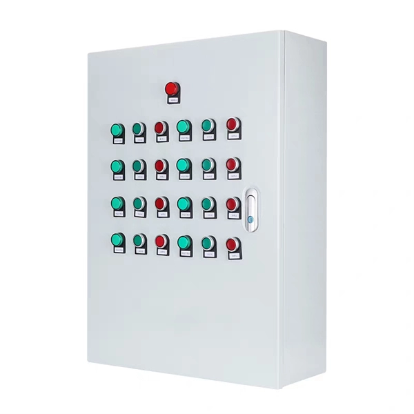
This AutoCAD DWG file includes a complete Single Line Diagram (SLD) of a Distribution Board, showing circuit breakers, wiring connections, and load distribution for lighting, power, and mechanical systems. An electrical panel box, also known as a breaker box or a distribution board, is a crucial component of any electrical system. It serves as a central hub for distributing electricity throughout a building, ensuring that power is delivered safely and efficiently to all the required locations. Whether you're an electrician or a DIY enthusiast, this guide will help you understand the basics of home electrical distribution. What is Distribution Board? Distribution board. Welcome to our channel @Electricalgenius In this video, we'll take you through a detailed step-by-step guide on wiring a home distribution DB (Distribution Board) box. A distribution board (also known as a service panel or breaker box) is a centralized collection of circuit breakers, fuses, and/or relays used to control and protect the wiring in a home. The diagram. To understand how a breaker box works, it is helpful to have a wiring diagram that shows the connections between the various components. At the heart of a breaker box is the main breaker, which controls the flow of electricity from the utility into the building. This breaker is connected to a.
[PDF]
Time domain reflectometers are commonly used for in-place testing of very long cable runs, where it is impractical to dig up or remove what may be a kilometers-long cable. They are indispensable for preventive maintenance of telecommunication lines, as TDRs can detect resistance on joints and connectors as they corrode, and increasing insulation leakage as it degrades and absorbs. OverviewA time-domain reflectometer (TDR) is an electronic instrument used to determine the characteristics of by observing. It can be used to characterize and locate faults in metallic cables (for. A TDR measures reflections along a conductor. In order to measure those reflections, the TDR will transmit an incident signal onto the conductor and listen for its. If the conductor is of a uniform.
[PDF]

This section provides an overview for busbars as well as their applications and principles. Here are the top-ranked busbar companies as of May, 2026: 1. Chatsworth. Busbars also known as bus bars, barra electrica, or busbar electrical systems are essential components in modern electrical distribution. Whether used in industrial bus bars, EV charging, renewable energy plants, or building infrastructure, busbars offer compact, efficient, and safe current. High Voltage Busbars are critical components in electrical power systems, designed to conduct high voltage electrical currents efficiently and safely. They are used in substations, switchgear assemblies, and electrical distribution systems to connect different parts of the system and manage the. According to Mordor Intelligence, the busbar market was valued at USD 5. 3 billion in 2023 and is projected to reach USD 7. 5% during the forecast period. What. The global busbar market will expand at a great rate and reach USD 19. 24% between 2023 and 2033. The top companies in busbar market are Siemens AG, Connectivity, Mersen, Schneider Electric, Rogers Corporation, Legrand.
[PDF]
In electric power distribution, a busbar (also bus bar) is a metallic strip or bar, typically housed inside switchgear, panel boards, and busway enclosures for local high current power distribution, transmission, or switching substations. They are also used to connect high voltage equipment at electrical switchyards, and low-voltage equipment in battery banks. They are generally uninsulated, and h. Design and placementThe busbar's material composition and cross-sectional size determine the maximum current it can safely carry. Busbars can have a cross-sectional area of as little as 10 square millimetres (0.016 sq in), but. • – Data transfer channel connecting parts of a computer• – Low resistance electrical conductor for high current transmission and distribution• – Modular approach t. • Elmore, Walter A. (1994). Protective Relaying Theory and Applications. Marcel Dekker.• Paschal, John (2000-10-01). Electrical Construction & Maintenanc.
[PDF]

They take power from one main source and safely channel it to multiple circuits within electrical enclosures like switchgear, panelboards, and distribution boards, replacing many individual cables. Busbars are fundamental workhorses in power distribution. In electric power distribution, a busbar (also bus bar) is a metallic strip or bar, typically housed inside switchgear, panel boards, and busway enclosures for local high current power distribution, transmission, or switching substations. They are also used to connect high voltage equipment at. Current Rating: Each busbar is rated for a specific current capacity to match system requirements. This setup allows busbars to distribute large currents safely, making them vital in high-power applications. Busbars come in various forms, each suited to different applications depending on the power. Whether it's a high-voltage substation or a low-voltage battery bank, busbars ensure seamless power flow, connecting incoming and outgoing feeders effortlessly. They're not just about distributing electricity; they're about doing it faster, and safer. With modern systems demanding higher efficiency. A busbar is essentially a strip or bar of conductive metal, usually copper or aluminum. In simple terms, a busbar is a common node where multiple incoming and outgoing circuits connect. Typically made from conductive materials like copper, aluminum, or brass, busbars.
[PDF]

The price of FRP trays can range from $10 to $50 per meter, depending on the specifications such as size, design, and environmental factors. Cable trays are vital in electrical installations, providing secure pathways for power, communication, and control cables across residential, commercial, and. Using 3/4" conduit for each cable at. 34/ft using 20 ft sections in tray and 10 ft sections for the drop. 21/ea for every 6 ft of cable for the drops and conduit couplers at. Understanding the key factors that influence their pricing helps engineers, contractors, and. This guide covers the critical steps, from selecting the right electrical cable tray and performing accurate cable fill calculations to managing a safe cable pull through and ensuring all bonding and grounding requirements are met. For licensed electricians, mastering these principles is essential. Market context (at-a-glance): Industry analysts valued the global low voltage wire & cable market at roughly USD ~ 145. 7 billion in 2024 and is projected to grow at a CAGR of 7. 2% from 2025 through 2034. Nearly 70% of new homes are now built with low voltage systems (industry estimate) meaning that. Ladder type cable trays are built for heavy-duty routing. In power-heavy areas, they prevent failures that would be far more expensive than the tray itself. Perforated cable trays sit in the middle. They cost less than ladder.
[PDF]
Voltage level: Industrial facilities often use multiple voltage levels (such as 1kV, 10kV, 400V), and it is necessary to ensure that the cable distribution box layout separates different voltage systems to avoid interference. A distribution box is the heart of any electrical system. It takes the incoming power and safely distributes it to different circuits throughout your building. Whether in a home or an industrial facility, this box keeps your electrical setup organized, functional, and efficient. However, the key to. Design requirements for low voltage distribution boxes cover NEC, IEC, and safety standards to ensure reliable, compliant electrical installations. You must make safety your top priority when working with low voltage distribution boxes. Protection requirement: According to the fault risk (such as short. For Branch Circuits (the conductors spanning from the final overcurrent device or breaker to the actual outlet, light fixture, or equipment), NEC Informational Note No. 4 recommends a maximum voltage drop of 3%. This ensures that the device at the end of the line receives at least 97% of the panel. For distribution boxes that handle only lighting circuits or small power loads, if the incoming wire size is less than 10 square millimeters and the number of circuit switches is fewer than 20, the width of the box should be calculated by summing the width of the switches and adding an additional.
[PDF]

West Port Middle East specializes in engineering and supplying cable management solutions that meet the precise requirements of electrical contracting projects across the GCC. Unigroup offers a line-up of high-performance cable trays, Trunking and Channel Systems for all your cable routing requirements. Our cable tray systems are engineered for modern infrastructure, ensuring safe, organized, and efficient cable routing across commercial, industrial, and utility. Cable Trays are support systems used in building electrical wiring. These cable support systems are commonly used to support insulated power and communication cables. Cable trays provide a more preferable alternative to electrical conduit systems and open wiring. Cable tray systems are generally. Premium Construction: Made from galvanized steel, stainless steel, or aluminum, these trays resist corrosion and provide high load-bearing capacity in harsh conditions. From residential towers to industrial plants, our extensive portfolio of products and accessories is designed to provide. A form of cable management system used for supporting and arranging electrical cables and wires in commercial, industrial, and residential structures is known as GI Cable Tray, also known as Galvanized Iron Cable Tray.
[PDF]