A Distribution Box, commonly known as a DB Box, serves as the central point for safely distributing electrical power from a main supply to multiple downstream circuits. It houses protective devices such as circuit breakers or fuses, ensuring both equipment protection and user. At its core, a DB Box is an essential part of any electrical system. Think of it as the heart of the electrical network, responsible for distributing electricity safely and efficiently from a central source (like a main power line or generator) to various circuits within a building or facility. Today, electrical systems are essential for homes and industries. But what exactly is a power distribution box, and why is it so essential in our daily lives? The DB panel board controls the flow of electricity. Each circuit is protected by its own circuit breaker. You will typically find panelboards in residential, commercial, and light industrial settings, often flush-mounted on. This ultimate guide explains what a distribution box does, its internal components, common types, real-world applications, and how to select the right DB Box for your project. We also highlight how reliable manufacturers like NUOMAK support stable, compliant, and cost-effective power distribution. Distribution boxes, or electrical junction boxes as they are sometimes called, play a vital role in electrical systems. The boxes also store protective equipment devices.
[PDF]
USB keyboards, mice, and I/O devices are the most common devices connected to a KVM switch. The classes of KVM switches discussed below are based on different types of core technologies, which vary in how the KVM switch handles USB I/O devices—including keyboards, mice, touchscreen displays, etc. (USB-HID = USB ) USB Hub Based KVM Also called an Enumerated KVM switch or USB switch selector, a connected/sh.
[PDF]

Synchronous Digital Hierarchy (SDH) is a standardized technology used in optical communications to transmit digital signals over long distances with high reliability and efficiency. Developed in the late 1980s by the International Telecommunication Union (ITU), SDH was designed to replace the. TL;DR: An SDH Optical Terminal (or Terminal Multiplexer) is a critical network device that aggregates multiple lower-speed electrical signals (like E1/T1 lines) into a single, high-speed optical signal for transmission over fiber optic cables. What is SDH Optical Terminal? With the advancement of. Synchronous Optical Networking (SONET) and Synchronous Digital Hierarchy (SDH) are standardized protocols that transfer multiple digital bit streams synchronously over optical fiber using lasers or highly coherent light from light-emitting diodes (LEDs). While SONET is predominantly used in North America, SDH serves. This article explains the Synchronous Digital Hierarchy (SDH) and its different levels, including STM-0, STM-1, STM-4, STM-16, STM-64, and STM-256, focusing on their bit rates and their relationship with E1 and E4 carrier systems. Developed to standardize high-speed data transport, SDH provides a robust and efficient method for moving vast amounts of digital information over long distances.
[PDF]

What is a Full Beam Log Splitter? A full beam splitter features a longer steel beam that runs from the front of the machine (where the splitting wedge is located) to the back (where the hydraulic cylinder mounts). A beam splitter or beamsplitter is an optical device that splits a beam of light into a transmitted and a reflected beam. It is a crucial part of many optical experimental and measurement systems, such as interferometers, also finding widespread application in fibre optic telecommunications. In its. What is the difference between a full beam and a half beam log splitter? This distinction may seem small at first, but it can significantly impact the ease of use, portability, durability, and performance of your log splitting operation. Beamsplitters are often classified according to their construction: cube or plate. 📦 For purchasing, use the RP Photonics Buyer's Guide for beam splitters. It provides an expert-curated supplier directory, buyer-focused technical background information, and structured selection criteria to support professional procurement decisions. The 2 forms of beamsplitters are cube and plate type. Circular beamsplitters, plate beamsplitters and cube beamsplitters can be purchased for polarizing or non polarizing beamsplitting.
[PDF]

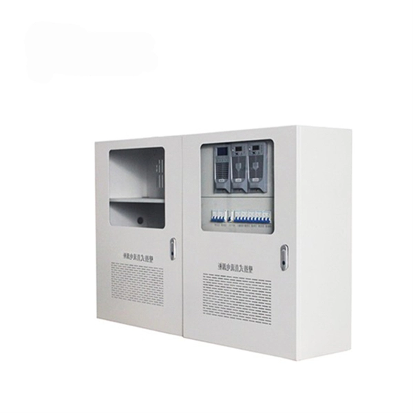
A distribution box is a key part of electrical systems in buildings. Inside, you'll find parts like circuit breakers and fuses that protect the system from problems like overloads and short circuits. Learn about the internal structure of a distribution box, its components, functions, and key types. But what exactly is a power distribution box, and why is it so essential in our daily lives? The DB panel board controls the flow of electricity. Also called a distribution board, panel board, breaker panel, or electric panel, it is the central hub in an electrical system that divides incoming power into various subsidiary circuits. It integrates power distribution, protection, and monitoring capabilities, and is responsible for distributing power to entire commercial or residential. The internal structure of the distribution box is designed to safely distribute power from the main power source to multiple branch circuits. It provides convenience for protection, control and maintenance. This article discusses the construction of the distribution box, its functional divisions. A distribution boxes is an essential device that manages the safe and efficient flow of electrical power throughout different areas of a building or facility. Understanding its significance.
[PDF]
The ZN151 - Abrites Distribution Box Set is a proprietary set of a Distribution box device with accompanying cables and pins, allowing the AVDI to connect to different vehicles and modules, with CAN and K-Line protocols. It provides in-vehicle connection options, as well as bench. ABRITES Distribution Box Set (ZN151) is an assisting tool, designed to work with AVDI interface and ABRITES diagnostic software for reading/writing electronic control modules flashes by direct connection and boot mode. The Distribution Box is convenient for working both on bench and in the vehicle. It provides in-vehicle connection options, as well as bench and boot mode.
[PDF]

Numerous disciplines, including photonics, telecommunications, biomedical imaging, and quantum computation, make extensive use of cube beam splitters and their techniques for manipulating light. A beam splitter or beamsplitter is an optical device that splits a beam of light into a transmitted and a reflected beam. It is a crucial part of many optical experimental and measurement systems, such as interferometers, also finding widespread application in fibre optic telecommunications. A typical cube beam splitter consists of two prisms with right-angle faces that are joined at their hypotenuses. A special dielectric coating is applied to one of these surfaces, which. 📦 For purchasing, use the RP Photonics Buyer's Guide for beam splitters. It provides an expert-curated supplier directory, buyer-focused technical background information, and structured selection criteria to support professional procurement decisions. What are Beam Splitters? A beam splitter (or. Plate beamsplitters are flat substrates with a partially reflecting coating on one surface that divides the optical beam based on power or wavelength. No epoxy or optical contacting is used in fabrication, making plate beamsplitters intrinsically suitable to high energy applications. They come in different types and have numerous applications. However, most do not know how they work.
[PDF]

Fiber optic module Also known as optical modules or optical transceivers, it is a pluggable interface module used in fiber-optic communication. When it comes to optical modules, I'm sure everyone is quite familiar with them. With the rapid development of optical communication,many scenarios in our work and life have now achieved "fiber replacing copper. Optical modules typically have an electrical interface on the side that connects to the inside of the system and an optical interface on the side that connects to the outside. What is a fiber optic module? A comprehensive guide to its working principle and common applications In today's information society, the speed and stability of network transmission directly determine the efficiency and competitiveness of businesses. Whether it's the high-speed interconnection in. Optical modules are compact devices that convert electrical signals into optical signals and vice versa. They are used in fiber optic communication systems to transmit data over long distances with minimal loss and interference.
[PDF]
The main types of network security devices include firewalls, intrusion protection systems (IPS), unified threat management (UTM) systems, network access control (NAC), email security gateways, web application firewalls (WAF), and VPN gateways. Network security involves tools, techniques, and policies to protect digital assets from unauthorized access and cyber threats. It combines hardware, software, and expert resources to ensure network integrity and prevent breaches. A key strategy in network security is the multi-layered defense. Network Security devices are typically physical or virtualized hardware appliances, with vendor specific software installed. Firewalls Firewalls act as the first line of defense in network security. These devices act as barriers between the internal network and potential threats from the outside world. Whether you're a business owner or an IT professional, understanding the. A Growing Attack Surface: Every connected device; laptops, servers, IoT devices, peripherals, and physical access points represents an entry vector attackers can exploit. Diverse Threat Actors: From opportunistic hackers and organized crime groups to nation-state actors and insider threats. Network security devices are essential for protecting your network from cyber threats.
[PDF]
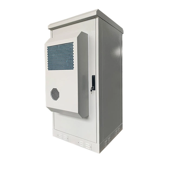
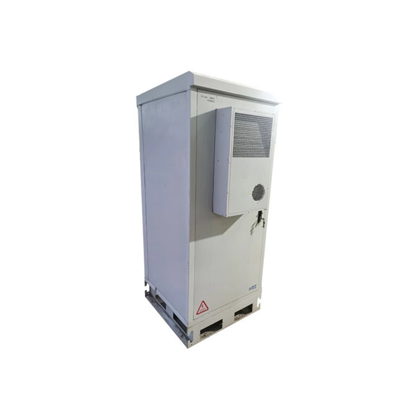
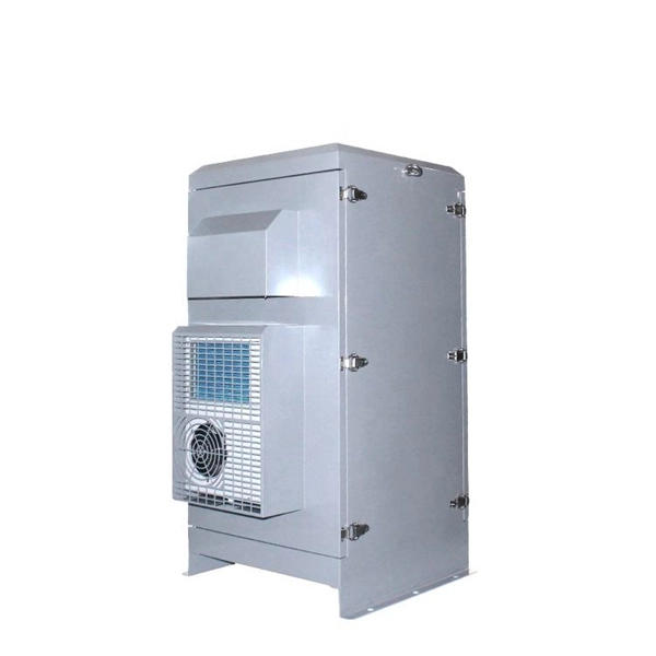
Look for boxes made from durable, weather-resistant materials. Plastic or fiberglass options often provide better waterproofing than metal ones. If you're unsure, consult with a professional or check product specifications to understand the waterproof ratings. Next, inspect the. A waterproof distribution box is an essential component used in various electrical installations to protect wiring and equipment from water damage. Typically constructed from durable, corrosion-resistant materials, these boxes are designed to withstand exposure to moisture and harsh environmental. What are the effects of chemicals on waterproof distribution boxes? The primary effects of chemical exposure on a waterproof electrical box include material degradation, stress cracking, and the loss of sealing integrity. Depending on the material (ABS, Polycarbonate, or Stainless Steel), contact. What is the difference between thermoset and thermoplastic materials? You can find distribution boxes made from various distribution box materials such as steel, aluminum, PVC, polycarbonate, high-density polyethylene, and thermoset plastics like SMC. These enclosures serve not only industrial applications but are also crucial for residential and commercial settings.
[PDF]
You use a fiber distribution panel to keep fiber optic cables organized. This panel helps you manage cables in your network. The panel protects connections from dust and water. It also shields them from changes in temperature. With the growth of the fiber industry, a wide array of fiber optic patch panels have been developed to fit the many needs of these varying environments. If you already know what your project requires, check out our complete Fiber Patch Panel selection. What is a Fiber Patch Panel? Fiber optic patch. A fiber patch panel is a mounted enclosure—either rack-mounted or wall-mounted—used to terminate, manage, and interconnect multiple fiber optic cables. It acts as a hub for organizing splices and patch cords, streamlining fiber management and preserving signal integrity. You use this device to connect and separate fiber cables. It lets you reach each fiber connection easily.
[PDF]
Step-by-step cable tray and conduit installation method with safety, quality and inspection procedures as per IEEE standards. But before you lay the first tray or clamp down a single cable, you need a solid plan. This guide breaks down the process step by step. Plan the Route Before You Drill No installation should start without a plan. Mark the cable tray route based on your electrical cable tray design and site. This guide covers the critical steps, from selecting the right electrical cable tray and performing accurate cable fill calculations to managing a safe cable pull through and ensuring all bonding and grounding requirements are met. For licensed electricians, mastering these principles is essential. This method statement describes a detailed procedure for properly installing cable trays and conduits for the Feeder System. The objective is to ensure safety, quality and compliance during the. Below is the detailed cable tray installation method statement not only for cable tray but also applicable for GI ladder and trunking for indoor and outdoor applications and in service rooms like pump rooms, electrical rooms and plant rooms etc. The Cable Tray system is installed in electrical rooms, plant rooms, and service corridors. The key requirements for cable tray installation include: Incorrect installation can lead to overheating, cable damage, or system failure. This is why proper planning and execution are.
[PDF]

A distribution boxes acts as the load center and main distributor of electrical power within a building. Each. What is a distribution board? In practice, when engineers ask “what is the distribution board”, they refer to an assembly that houses switching devices, protective devices, and busbars within a single enclosure. A typical power distribution board or distribution panel board receives power at the. Eaton's comprehensive range of power distribution solutions have been developed to meet today's challenging electrical sub-distribution applications in commercial and industrial buildings. It integrates power distribution, protection, and monitoring capabilities, and is responsible for distributing power to. ●Series:SP-S ●Material:Polycarbonate ●IP Rating:IP66 ●NEMA Rating:4X ●Color:Light Grey ●Application:Outdoor ● Waterproof,dustproof,anticorrosion,highstrength insulation Any opening isavailable according to the customersʼ demands,it isvery complete in specification and convenient in installation. Today, electrical systems are essential for homes and industries. But what exactly is a power distribution box, and why is it so essential in our daily lives? The DB panel board controls the flow of electricity.
[PDF]