
The required clearance in front of the panel depends on what's directly facing it on the opposite wall: 36" – If facing a non-electrical wall. 42" – If facing a grounded surface (e., concrete or brick). Grounded surfaces can complete a circuit, so more risk means more depth. The National Electrical Code (NEC) provides comprehensive safety standards for electrical installations, including requirements for electrical panels (main service panels and subpanels or breaker box). NEC Article 408 covers switchboards, switchgear, and Panelboards installation and applications. Learn how to install a distribution box safely and correctly. It takes the incoming power and safely distributes it to different circuits throughout your building. The National Electrical Code provision 110. 26 clarifies that. Electrical panel boxes, aka breaker boxes, can be on a wall in an out-of-the-way area of your home. You can find electric panels inside cabinets, behind refrigerators, or inside clothes closets in older homes. Electrical panels. Everything you need about the wire and cable market, visualized. The panel should also have space for efficient. Electrical clearances are the minimum separation distances the National Electrical Code (NEC) requires between wiring, panels, overhead conductors, and everything around them. These rules exist to prevent electrocution, fire, and equipment damage.
[PDF]
This guide will walk you through every step of the process, from selecting the right materials to securing connections and ensuring safety. Whether you're a seasoned professional or an enthusiastic DIYer, our detailed instructions will equip you with the knowledge and confidence to tackle this. Learn how to properly install an electrical box safely and efficiently. In this step-by-step tutorial, we'll cover: ✅ Tools you need. Covers wiring, placement, standards, and expert tips for a compliant setup. A distribution box is the heart of any electrical system. It takes the incoming power and safely distributes it to different circuits throughout your building. A neutral bar kit is a fundamental component within an electrical service panel, often called a breaker box, designed to manage the flow of electricity in a home or building. This metal strip serves as the termination point for all neutral conductors from the branch circuits. By consolidating these. Before starting the installation, finding a proper place for putting the distribution box is crucial, because it largely decides the safety and convenience of maintenance. Let's see what factors need to be taken care of when choosing the installation place. Beginning of dialog window. Escape will cancel and close the window.
[PDF]

In this guide, learn the basics of reading and interpreting electrical wiring diagrams. Follow Along on SkillCat: "Wiring Diagrams" Course! Want to test your knowledge? Skip to the quiz!. In this article, you'll learn how to read, understand and use a wiring diagram. An electrical wiring diagram could be a single page schematic of how a ceiling fan should be connected to the power source and its remote switches. A wiring diagram may include the wirings of a vehicle. For example, how. Electrical wiring diagrams are an essential tool for electricians, engineers, and automation technicians. Proper interpretation is crucial for understanding the operation of devices, diagnosing faults, and working safely with electrical installations. Understanding how to read electrical diagrams. In order to trace control system problems to the core, the ability to read and interpret various resources, from facility-level diagrams to machine-level wiring layouts, is critical. The engineering world is crammed full of drawings and diagrams of every possible kind. It shields sensitive equipment from dust, moisture, and. After reading and studying this handbook, electricians (or would-be electricians) will have a firm grasp on the many symbols used in electrical diagrams.
[PDF]

Cable TypePrice Range (USD/meter)Simplex / Duplex Indoor Cable$0. 30Single-mode Outdoor Cable$0. 50Multimode (OM1/OM2/OM3)$0. 60Armored Cable (Steel Tape / FRP)$0. 50 These are indicative prices. Buyers typically pay for fiber optic cable by length, fiber type, and installation complexity. Main cost drivers include cable grade (indoor vs outdoor, armoured), distance, and labor for trenching, splicing, and termination. Data aggregated from Q1 2026 contractor invoices across Texas, Ohio, and North Carolina. Cost per foot of fiber. How Much Does Fiber Optic Installation Cost Per Foot? Cable Material Costs: Installation Costs by Method: Prices can range from $1 to $50+ per linear foot depending on the method and complexity. The initial cost of installing fiber optic cables can vary depending on the chosen installation method. Cable installation price refers to the total cost of deploying fibre or copper cabling across a site. It includes labour, materials, termination methods, routing complexity, and any environmental factors such as trenching or conduit work. When you plan a structured cabling project, the cost of. Because the core is wider and harder to manufacture to 2025 standards, it's a jump in price: $1. Armored cables: If there's any chance of a shovel or a rat hitting that line, you need steel tape armor. That “insurance” That 'insurance' bumps the price to $1. 50 per meter, depending on several variables.
[PDF]

Plan your outdoor fiber installation carefully by surveying the site, choosing the right cable type, and following FOA and OSP standards to ensure reliability. Select the best installation method—direct burial, aerial, conduit, or underwater—based on your environment and. Underground cables are pulled in conduit that is buried underground, usually 1-1. 2 meters (3-4 feet) deep to reduce the likelihood of accidentally being dug up. In extreme cold climates, cables may need to be buried at greater depths where there temperatures are colder and frost penetrates to. We are Jera line, a factory that produces cable infrastructure products. FODB-8 is installed with adapters, splitters, drop cable patchcords, pole bandings, and fiber cable slack storage. Use. pport cables and splice enclosures. Cost of rack Wire Splice B x (200 (50' Mi As ve 1'-0" wide (min) concrete apron. rons shall be sloped away from box. Cost of apron o d oun. FTTP or fiber To The Premises applications have reinforced the importance of reliable and stable fiber optic terminations. Good quality fiber laying and termination systems help achieve minimal back reflection and low signal loss. They also feature resistance to moisture, impact, chemical exposure. Fiber optic cable may be installed indoors or outdoors using several different installation processes. Outdoor cable may be direct buried, pulled or blown into conduit or innerduct, or installed aerially between poles.
[PDF]

This guide summarizes field-proven rules for AI/AO/DI/DO wiring, shows how to choose between NO/NC contacts under the fail-safe principle, and explains how to decode typical cable schedule entries. Instrument installation with the associated cable installation/electrical signal and control wiring should be carried out by skilled personnel who are acquainted with the safety requirements and regulations for the plant site for that specific project. Generally instrument cabling is usually run in. Few factors are to be considered or taken care of while wiring a field instrument to control panel. Based on noise susceptibility limits (NSL) according to IEEE 815 standard, various field instrument signals are classified as below. Noise Susceptibility Limit Grounding of the signal cable Type of cable Cable Terminations Based on noise susceptibility limits (NSL). Note how the hoop-shaped “jumper” wires are all cut to (nearly) the same length, and how each of the wire labels is oriented such that the printing is easy to read: This next photograph shows a great way to terminate multi-conductor signal cable to terminal blocks. Each of the pairs was twisted. A well-designed and properly installed instrument junction box is crucial for the efficient operation and maintenance of electrical systems. Level 1: High to medium susceptibility Level 2: Low susceptibility.
[PDF]

This video shows real on-site footage of electrical installation, demonstrating safe and standardized wiring methods used by professionals. Covers wiring, placement, standards, and expert tips for a compliant setup. A distribution box is the heart of any electrical system. It takes the incoming power and safely distributes it to different circuits throughout your building. In this video, we'll walk you through the process of wiring a home distribution box with a detailed connection diagram. Whether you're an electrician or a DIY enthusiast, this guide will help you understand the basics of home electrical distribution. It has three categories: residential, commercial and industrial electrical distribution boxes, all of which play important roles in their respective electrical. This guide aims to provide a comprehensive overview of double wide mobile home electrical wiring diagrams, covering everything from the main service panel to individual circuits. This panel is. Box installation: Make sure that Distribution box has been correctly installed and fixed. Material preparation: Prepare the required circuit breakers, wires, wiring ties and other materials, and ensure that they meet the design drawings and installation requirements. Location determination:.
[PDF]

The fiber cores of GYTC8S53 fiber cable is from 2 cores to 288 cores GYTC8S53 is a self-supporting fiber optical cable for outdoor use. Commonly referred to as figure 8 cable, figure 8 fiber cable, figure 8 aerial cable, self-supporting figure 8 cable, or simply figure 8 optical cable, this ingenious structure combines optical fibers with an integrated messenger wire in a distinctive “8” cross-section. This self-supporting design. Hunan GL Technology Co., Ltd Supply 2-144 Cores GYFTC8S Aerial Stranded Figure 8 Fiber Optic Cable With Factory Price, Support OEM, All the figure 8 cables supplied from GL FIBER are complied with IEC 60794-4、 IEC 60793、TIA/EIA 598 A standards. In the GYFTC8S cable, single-mode/multimode fibers are. GYTC8Y is a typical self supporting outdoor fiber optic cable with features of moisture resistance and crush resistance suitable for aerial application. The stranded wires as the supporting part are completed with a polyethylene (PE) sheath to be figure 8 structure. After being coated with steel tape longitudinally, a layer of PE inner sheath is extruded, and then a single layer or double layer thin round steel tape armor is longitudinally wrapped After installation, the. l fibers in loose tubes filled with interstitial gel. Aluminum moisture barr er tape or steel tape armoring options are availa le. A steel messenger wire provides tensile strength. It can work at the temperature from -10 to +70℃.
[PDF]

The good news is that network cabinet prices range from as low as $100 for basic wall-mounted units to over $3,000 for specialized outdoor models. However, understanding what drives these costs will help you make a smart buying decision. In this complete guide, we'll break down everything you need. Check each product page for other buying options. VEVOR 6U Wall Mount Network Server Cabinet, 15. 5" Deep, Server Rack Cabinet Enclosure, 200 lbs Max. 5". Explore our top-tier selection of Networking Cabinets and Racks designed to keep your IT infrastructure organized and secure. Whether you're setting up a home lab, a corporate data center, or managing network equipment for a small business, our collection offers robust and versatile solutions. Cabinets are used for storing routers, patch panels, switches and a wide variety of networking equipment and accessories. Network cabinets support large, modular network switches by providing additional space for cable management and. Network cabinets are enclosed systems designed to securely store, organize, and protect networking and IT equipment such as switches, routers, patch panels, servers, power strips, and cable management components. They allow users to secure their data and communication connections. The product will be reserved for you when.
[PDF]

Connect the phase and neutral wires from the input power supply to the input of the Main MCB. Learn how to install a distribution box safely and correctly. Covers wiring, placement, standards, and expert tips for a compliant setup. It takes the incoming power and safely distributes it to different circuits throughout your building. Learn how to wire a distribution box step by step! This video shows real on-site footage of electrical installation, demonstrating safe and standardized wiring methods used by professionals. Below is a quick checklist of everything you will need for a safe and efficient installation: Connecting a distribution box involves several steps to ensure proper electrical flow. It is usually equipped with circuit breakers, fuses, terminal connectors, and other components. It is mainly used to isolate fault circuits, prevent overload, and ensure the safe operation of. Box installation: Make sure that Distribution box has been correctly installed and fixed. Location determination:. An electrical panel box, also known as a breaker box or a distribution board, is a crucial component of any electrical system. It serves as a central hub for distributing electricity throughout a building, ensuring that power is delivered safely and efficiently to all the required locations.
[PDF]

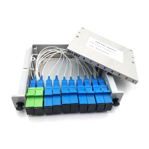
Insertion loss tells you how much weaker the signal becomes after passing through the splitter. Let's say you have a laser output at 0 dBm (which is 1 milliwatt of optical power). If you use a 1×8 splitter with ~10. 5 dB of insertion loss, the power at each output would be: 0 dBm – 10. 5. Enter excess loss from the splitter datasheet for your wavelength. Add connector and splice quantities with realistic planning losses. Include any additional component losses and an engineering margin. Enable power budget to estimate received power and margin. Press Calculate to show results above. Understanding optical splitter loss isn't just about plugging numbers into a calculator. It's about knowing what factors contribute to that loss, how manufacturers specify it, and how it impacts the overall performance and reach of your network. Ignore it, and you might find your signal too weak to. Optical insertion loss refers to the signal loss resulting from the insertion of components such as connectors or splices in an optical fiber system. Common ratios: For cascades, add losses and validate margin using the Optical Budget tool. This Fiber Optic Splitter Insertion Loss is the splitter devices loss, Considering fiber connectors or connectors+adapter insertion loss in LGX, The fiber splitter IL would be a little bigger. To make clear the basic ftth fiber splitter loss in performance, You can refer to the below loss chart.
[PDF]

This video shows you how to build a 10Gbps fiber optic network between buildings using PoE+ switches, SFP+ transceivers, and link aggregation for even higher speeds (up to 40Gbps!). Modern network infrastructure depends on fiber aggregation switches to combine several fiber optic links into one streamlined network connection. They are built to handle large amounts of data flowing through them without interruptions over long distances. more Need to transfer. With AXIS D8308 Fiber Aggregation Switch you can connect multiple Axis devices using fiber midspans over long distances. It also enables easy expansion by simply adding more fiber or network switches. Long-distance installations often require fiber optic cables to connect different sites because of. The Cisco ASR 920 Series Aggregation Services Router is a family of fixed configuration routers that enables Service Providers to provide business, residential, and mobile access services to their users. It is the Carrier Ethernet access platform providing Ethernet services. The Cisco ASR 920. This manual provides detailed instructions for the installation, operation, and maintenance of the Ubiquiti Networks UniFi Aggregation Switch, model USW-Aggregation. Fibers in these points are either spliced.
[PDF]

As a key parameter for evaluating data transmission accuracy, the bit error rate directly determines the reliability and stability of communication systems. This article delves into the fundamentals and testing methods of the bit error rate. A bit error occurs when a single binary digit is flipped during transmission, meaning a logical '0' is mistakenly interpreted as a '1' by the receiver, or a '1' is read as a '0'. Through the interpretation of actual test reports, it. BER is calculated by comparing the transmitted sequence of bits to the received bits and then counting the number of errors. The ratio of how many bits received in error over the total number of bits received is the BER. This ratio is affected by many factors including: signal to noise, distortion. Bit Error Rate (BER) is a crucial metric in signal processing and communication systems, measuring the frequency of errors in data transmission. It is defined as the ratio of the number of bits received in error to the total number of bits transmitted over a communication channel during a specified. In the fast-paced world of digital communication—where billions of bits travel through wires, fibres and wireless links every second—the concept of bit error rate (BER) is both fundamental and profound. It involves measuring the rate at which errors occur in a transmitted bitstream compared to the expected bitstream at the receiver end. The BER measurement helps in assessing the quality.
[PDF]