A 24-port patch panel is a networking device that allows for the organization and management of incoming and outgoing network connections. It acts as an interface between different devices such as computers, switches, and routers, allowing for easy connectivity and communication. This guide explains how to use a 24-port patch panel to manage copper and fiber cabling in a small LAN, how to choose between different patch panel types, how to design your cabinet layout, and why a patch panel is still irreplaceable in 2026. What is a Patch Panel and Why it Matters in 2026? A. Choosing a 24-port patch panel is crucial for efficiency. Learn how it enhances network capabilities. Typically, patch panels are available in a huge number of port densities from 12. In this article, we will define what a patch panel 24 port is, explain its purpose, and discuss why it is a crucial component in organising network cables. A patch panel 24 port is a device used in network cabling to connect and organise multiple network cables in one central location. It is a. Choose a 24-port patch panel when you care about clean labeling, comfortable “finger room,” and fast moves/adds/changes—especially if technicians touch the rack often and you want straightforward port-to-port mapping (Panel 01–24 ↔ Switch 01–24). Choose based on port density, cabinet space.
[PDF]

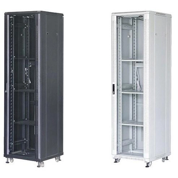
This guide provides essential best practices for server rack setup and organization, covering steps for effective installation, cable management, standards compliance, power distribution, cooling methods, and security measures. By following these practices, you can enhance your network's. An in wall network cabinet is a special type of enclosure that fits inside your wall. Unlike traditional floor-standing racks, these cabinets are recessed, which means they don't take up valuable floor space. They're designed to hold important networking equipment such as switches, patch panels. There are various options available, ranging from simple wall-mounted enclosures to larger floor-standing cabinets. Consider the amount of equipment you have and the future expansion needs when choosing the size of the cabinet. It should have enough space to accommodate your modem, router, network. Whether you're setting up a new office or streamlining an existing network, understanding the importance, types, and usage of network cabinets is crucial. In this comprehensive guide, we'll explore everything you need to know about network cabinets, transforming chaos into order in your network. Today, manufacturers are designing data equipment rated at 75W and 150W per square foot, and even higher because server vendors are introducing equipment as small as 1U in height-particularly with servers aimed at the Internet Service Provider (ISP) market.
[PDF]

Recommendation ITU-T L. 163 describes criteria for the installation of optical fibre cables defined in Recommendation ITU-T L. 110 in remote areas with lack of usual infrastructure for installation including the procedures of cable-route planning, cable selection, cable-installation. The Fiber Optic Association, Inc. (FOA) was founded in 1995 to help develop the workforce to build the fiber optic networks to support a rapid expansion in communications and the Internet. They define a minimum baseline of quality and workmanshi for installing electrical products and systems. NEIS® are intended to be referenced in contrac documents for electrical construction ation or liability to users of this publication. Existence. This section covers Agency requirements for fiber optic service entrance cables intended for aerial installation either by attachment to a support strand or by an integrated self-supporting arrangement, for underground application by placement in a duct, or for buried installations by trenching. National Electrical Installation StandardsTM are designed to improve communication among speci-fiers, purchasers, and suppliers of electrical construc-tion services. This Standard may also apply to the Jet Propulsion Laboratory other contractors, grant recipients, or parties to agreements PR 8735. 2, Hardware Quality Assurance Program Requirements for Programs and Projects.
[PDF]

Recommendation ITU-T L. 101 describes characteristics, construction and test methods of optical fibre cables for buried application. 0, in February 2016. First, in order to demonstrate sufficient performance of an. ion) and “ Installed” (after installation). The following formulas may be used to determine general guidelines for installing Corning Optical Communications fiber optic cable; however, refer to the cable specifi simply double the minimum working bend radius. Split cable guides and split 40-in. 1. The methods described are intended for guideline use only, as it is impossible to cover all the various conditions that may arise during an installation. Individual. The Fiber Optic Association, Inc. (FOA) was founded in 1995 to help develop the workforce to build the fiber optic networks to support a rapid expansion in communications and the Internet. The charter of the FOA was to promote professionalism in fiber optics through education, certification, and. Home / Instruction Sheets / Fiber Optic Cable Direct Burial Guidelines Need Help?. When planning a fiber optic network installation, one of the most common questions is: How deep are fiber optic cables buried? Proper burial depth is critical for the safety, durability, and performance of your communication infrastructure.
[PDF]

This guide explains what a fiber optic termination box is, how it works in practice, where it is typically installed, and how to choose the right model for different network environments. What Is a Fiber Optic Termination Box?. A Fiber Termination Box, also known as a Fiber Distribution Box, is a crucial component in fiber optic networks. It serves as a termination point for optical fibers, providing a secure and organized space for connecting and managing fiber optic cables. It functions as a junction between the incoming fiber cable and the outgoing customer-side fiber cable, where one fiber can be spliced, patched. A fiber optic termination box is a core component in modern fiber optic networks, providing a secure and organized point for fiber termination, splicing, and distribution. It is widely deployed in FTTH, FTTB, and other access networks to ensure stable signal transmission from backbone cables to end. Fiber termination box (FTB), also known as optical terminal box (OTB), generally refers to a distribution box specially designed for fiber cable management (fiber patch cables/pigtails) in FTTH applications. To ensure consistent performance and longevity, it is essential to adhere to strict technical specifications.
[PDF]
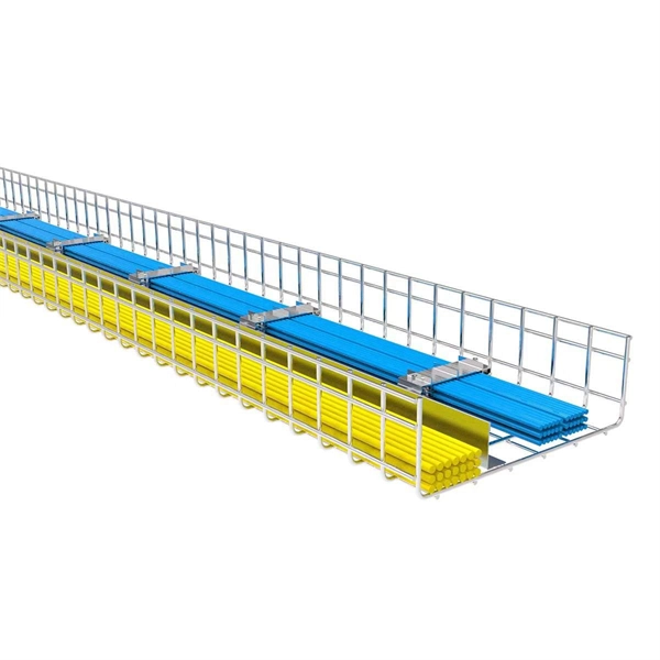
Standard splice plates can often provide a safe electrical path if they are UL Classified and bolted tight. However, you must use copper bonding jumpers if the tray is painted or has expansion joints for movement. A. The intent of this article is to review grounding practices for cable tray wiring systems. The Equipment Grounding Conductor is the electrical circuit's safety conductor. When designing a cable tray. Snap Track requires only single bonding jumper. Installation Guideline: Scroll to bottom of page to view All Bonding Jumpers Cut Sheets A bonding jumper is required to be installed with adjustable splices and expansion splices. If an EGC cable is installed in or on a cable tray, it should be bonded to each or alternate cable tray sections via grounding clamps (this is not required by the NEC® but it is a desirable practice). In addition to providing an. Do I have to use a bonding jumper at each cable tray splice point that is bolted tightly together? I currently have 3 runs of 24 tray about 80ft long. we have one expansion plate section per run in which I plan on using a bonding jumper at, I am curious about all other points You aren't even. Wire mesh cable trays are widely used in commercial offices, industrial facilities, data centers, and smart building infrastructure because they provide unmatched flexibility, excellent airflow, and fast, adaptable installation. Their open-grid design makes it easy to route, add, or modify cabling.
[PDF]
This document outlines the key requirements for cable tray layout, installation, and fireproofing in industrial and commercial environments. Route Planning and Layout Principles. Provides technical requirements concerning the construction, testing, and performance of metal cable tray systems. It is the first joint effort of NEMA and CSA International to put in one place standards for metal trays per both NEMA and CSA methods. Addresses shipping. Method Statement installation of Cable Trays and Ladders - Planning Engineer FZE. Whether you're designing a new. Below is the detailed cable tray installation method statement not only for cable tray but also applicable for GI ladder and trunking for indoor and outdoor applications and in service rooms like pump rooms, electrical rooms and plant rooms etc. All materials intended for cable tray, ladder and. Cable tray installation must comply with specific technical standards to ensure electrical safety, system reliability, and long-term maintainability. The mechanical and electrical characteristics, tests, certifications, overall quality management, recommendations mentioned in this technical guide only apply to our own cable management ranges and cannot under any circumstances be transpos regulations which.
[PDF]
Learn about the market conditions, opportunities, regulations, and business conditions in paraguay, prepared by at U. Embassies worldwide by Commerce Department, State Department and other U. agencies' professionals The standards regime in Paraguay includes obligatory and voluntary standards. The Group's environmental commitment is centred on 3 guiding lines: taking on board environmental management in the running of its industrial sites, reducing the environmental impact of its products by eco-design, providing environmentally friendly solutions that contribute to energy savings. Type. REV.
[PDF]

Start by separating your Ethernet cable into two separate cables and connecting them to the back of the Ethernet cable splitter. Once the cables are securely connected, connect the other ends to your desired devices. Ensure that the cables are tightly secure and that all connections. When you need to connect multiple wired devices like computers, printers, and IP phones, but only have one Ethernet wall port, using an Ethernet splitter or network switch can expand your connectivity without rewiring. This guide explains your options and helps you choose the best solution for your. An Ethernet splitter is a small device that allows two Ethernet-connected devices to share a single cable run. It does not increase speed or create extra bandwidth. It simply divides signal pairs. This tool works best in basic setups where running another cable is not possible. An Ethernet splitter. Ethernet cable splitter wiring diagrams are essential for anyone who needs to connect multiple devices in a home or office network. With the ever-increasing popularity of high-speed internet and streaming services, providing reliable connections to multiple devices is becoming increasingly. An Ethernet splitter doesn't actually split a single Ethernet connection to provide separate internet access to two devices. Instead, it utilizes only two of the four pairs of wires within a single Ethernet cable to connect two devices, requiring two splitters for the setup to function correctly.
[PDF]
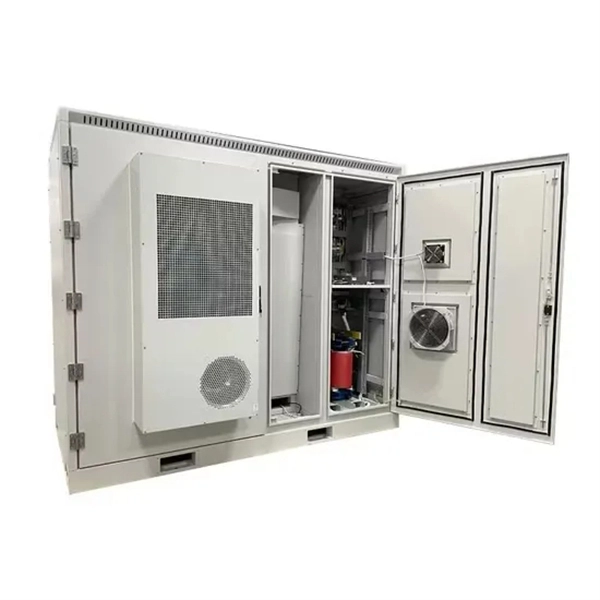
5G outdoor cabinets, also referred to as 5G cabinets or 5G enclosures, are boxes designed to house and protect the electrical equipment to support 5G-LTE technology. Made of metals, plastics or a combin.
[PDF]

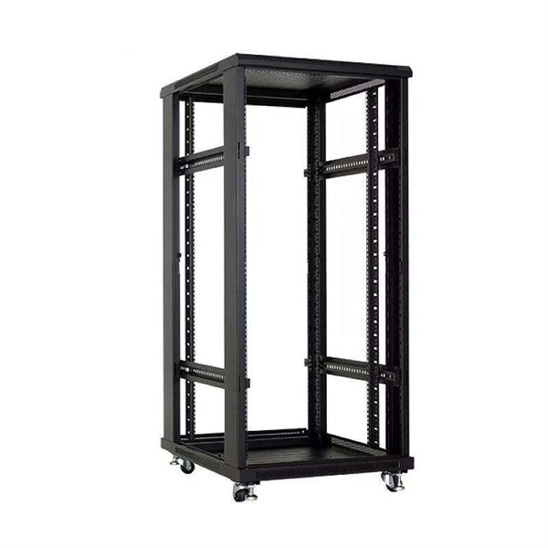
One rack unit equals 1. 45 mm), defined by the EIA-310. Measure your deepest server and add 3–6 inches for cabling and airflow. While rack height is standardized in rack units (U), external dimensions vary by manufacturer. A rack space calculator is a specialized tool designed to help data center professionals, IT administrators, and network engineers determine the optimal placement and space requirements for equipment in server racks. This calculator helps you plan rack layouts by calculating the total rack units. Server rack height is measured in rack units (U). Use the. When planning LAN infrastructure, selecting the correct data rack size is essential for proper equipment fit, ventilation, cable management, and future expansion. A practical formula often used for estimating the required rack size is: Rack size = 1. Common sizes: 42U, 48U, and compact options like 22U–27U. Standard width is 19 inches (EIA-310 compliant), while outer widths vary (e. Rack depth matters for. The three primary dimensions to consider are rack height (measured in rack units or U), rack width (most commonly the industry-standard 19-inch format), and rack depth (typically ranging from 24 inches to 48 inches). Each of these factors influences equipment fit, airflow management, cable routing.
[PDF]
An optics expert explains how thin strands of glass that transmit light make modern telecommunications possible. Fiber-optic communication is a form of optical communication for transmitting information from one place to another by sending pulses of infrared or visible light through an optical fiber. The light is a form of carrier wave that is modulated to carry information. The fiber which is used for optical communication is waveguides made of. Understanding Fiber Optic Communication System: Working, Components, and Advantages The need for fast, high-capacity data transmission is on the rise, thanks to 5G technology, cloud computing, and a growing number of data-intensive applications. Thin strands of glass bundled in cables and stretched across continents and oceans make possible much of what we take for granted today, such as the Internet, Zoom calls, electronic. Fibers commonly used in optical communication are single mode and GI. Figure 4: Examples of light transmission through different optical fiber types Table 1. Optical Fiber Characteristics and Applications Optical signal rate attenuation as it passes through quartz fiber varies depending on a. Fiber optics is also the basis of the fiberscopes used in examining internal parts of the body (endoscopy) or inspecting the interiors of manufactured structural products. The basic medium of fiber optics is a hair-thin fiber that is.
[PDF]

Shop 100Mbps Network Interface Cards on Newegg. Watch for amazing deals and get great pricing. Any questions? Our AI beta will help you find out quickly. PCIE x8 Interface to Dual 10GbE SFP+ Ports NIC Card, Intel 82599ES 10Gbps Ethernet Controller (X520-DA2) Need help? Discover high-performance fiber optic network interface cards for servers and desktops. Find single and dual port SFP+ adapters with reliable connectivity. Lot Of 45 Router Board RB 433 Free Shipping And Free Tracking!!! Great Price!! Only 1 left! Realtek Fast 200 RTL8139D 10/100M 10/100Mbps. Ethernet Network Lan Card Adapter Only 1 left! Only 1 left! Only 1 left! Only 1 left! Only 1 left! Get the best deals on 100Mbps Internal Network Cards and find. PCI-Express (PCI-E) 1. 0 compliant card installs easily in a PCI-E slot and includes Microsoft® certified drivers. Wake-On-LAN (WOL) power management supported via the PCI BUS. PCI-Express (PCI-E) 1. (Only one port may be in use at a time). This NIC is easily configured for half-duplex or full-duplex operation. Singlemode. Learn why IT Pros trust StarTech.
[PDF]