OSFP, or Octal Small Form-factor Pluggable, is a high-speed transceiver form factor designed for next-generation data center networking. Compared with previous generations of optical modules, OSFP is optimized for higher bandwidth, better thermal performance and denser port. Among the various 400G optical transceiver form factors, OSFP stands out as a next-generation form factor specifically designed for high-speed Ethernet, offering clear advantages. This article introduces the fundamental concept and key characteristics of 400G OSFP Ethernet optical transceivers, and. Optech, a Taiwan-based optical transceiver manufacturer, provides professional 400G OSFP and 800G OSFP solutions designed for AI, cloud, high-performance computing, data center and advanced networking applications. Understanding MSA is critical for compatibility validation, cost. As data centers transition from 400G to 800G interconnects, bandwidth demand, power efficiency, and thermal constraints have forced the industry to look beyond traditional form factors. Designed to support 400 Gigabit Ethernet transmission with improved thermal performance and higher power capacity, OSFP modules are widely adopted.
[PDF]

Islamabad, October 31, 2024 – Jazz, Pakistan's leading digital operator and a member of the VEON Group, has taken a significant leap in advancing the nation's telecommunications infrastructure by deploying a 400G IP-based RAN Access Optical Network in collaboration with Huawei. Islamabad, October 31, 2024 – Jazz, Pakistan's leading digital operator and a member of the VEON Group, has taken a significant leap in advancing the nation's telecommunications infrastructure by deploying a 400G IP-based RAN Access Optical Network in collaboration with Huawei. Huawei Technologies and Transworld Associates announced the successful deployment of Pakistan's first 400G optical network, a major milestone in the nation's digital infrastructure development. The cutting-edge network spans 72 sites nationwide, underscoring both companies'. Islamabad: In a landmark step toward Pakistan's digital transformation, Huawei Technologies and Transworld Associates on Wednesday afternoon announced the successful deployment of the country's first 400G optical network, significantly enhancing connectivity across the China-Pakistan Economic. Huawei provided a 400G solution designed for high bandwidth and low per-bit cost. Key features include: a. A CDF network architecture enables smooth evolution to higher speeds (400G+ and beyond) while facilitating L-band expansion for enhanced capacity. Delivering 400G per wavelength, each fiber.
[PDF]

Check CORE SWITCH price from the latest Cisco price list 2022. Extreme VSP 8600 switches are modular core platforms engineered for the largest enterprise and service provider environments. Built to deliver multi-terabit scale, these chassis systems support fabric-based architectures that simplify operations while ensuring high availability, resiliency, and. Core switches are the way toward the Network segment in the sense of managing the high-speed information flow and maintain the connectivity of the multiple network segments. Scalable Intelligent AMX switch Be the first!Command output number of the number of switches against its better performance. FI per port to connect to Nexus switches. 9Ghz, 6Core Broadwell DE CPU128GSSD,32GDRAM REMANUFACTURED. Cisco® C9350 Series Smart Switches deliver exceptional performance and robust security with flexible management options to meet the demands of modern enterprise networks. As the backbone of modern network infrastructure, it ensures fast, secure, and reliable data transmission between distribution switches, data centers, and external networks such. The market is segmented into core, distribution, and access switches, with core switches playing a pivotal role in managing high network traffic volumes and ensuring seamless connectivity within large-scale networks like data centers and enterprise environments 3 5. The market is projected to.
[PDF]
The state imposes a number of restrictions and requirements on the activities of foreign agents. As of March 2021, foreign agents in Russia are divided into three groups, which were defined by law in different years: • Non-profit organizations-foreign agents - since 2012. • Media-foreign agents - since 2017.
[PDF]

Switch cascading is a traditional method to interconnect multiple Ethernet switches. This technique involves various network topologies and allows users to configure and manage each switch independently within a group. Among the various topologies, daisy chain and star are the most. In the world of networking, Ethernet switches are integral components that provide the necessary interconnects for our devices. Sometimes, one switch is not enough to meet our needs, whether in terms of port number, specific functionalities, or both. Thus, multiple Ethernet switches are connected. Cascading is the traditional method of connecting multiple Ethernet switches. Cascading switches refers to the process of connecting multiple switches together in a series, effectively expanding the network's capacity and reach. This hierarchical connection allows for efficient and seamless. Connecting switches can be achieved through two common methods: cascading and stacking. Multiple switches can be cascaded in various ways as needed. In a larger local area network such as a campus network (campus network), a plurality of switches generally form a cascaded structure of a bus topology, a tree.
[PDF]

Network segmentation with switches involves dividing a network into smaller, isolated segments to enhance security, improve performance, and simplify management. Learn how to configure a switch for network segmentation effectively by using VLANs, subnetting, and access control lists (ACLs). You may. to communicate with each other. VLA h or complete physical network. When you physically separate a network, the devic s are assigned to a switch port. However, when a network is separated using VLANs, the devices are logically separated by n of the VLANs is not mandatory. VLANs can also extend. Explore how Versitron single fiber media converters support fiber optic packet forwarding, VLAN tagging, signal amplification, and robust network segmentation—ideal for scalable and secure data infrastructure. Setting up a VLAN on a fiber optic switch is very similar to setting up on any other type of switch, but it's important to make sure the switch supports VLAN functionality. The. By segmenting a network into VLANs, you will increase usable network bandwidth, resources, and performance through the reduction of broadcast traffic. Routers also break up broadcast domains. Routers operate at Layer 3, forwarding packets based on IP addresses, not MAC addresses. A router will. Step-by-step instructions for configuring VLANs using network hardware. Allocate unique segment identifiers directly through your device's interface to minimize broadcast domains and reduce.
[PDF]
These server racks are easy to build and made from materials you can find at just about any hardware store. Build a secure and sturdy server rack that fits all your equipment without spending so much money. Build your own home server rack with these 6 DIY plans. From wood to metal designs, learn how to organize your network gear efficiently and save money today. Whether. In this regard, These DIY server rack plans will help you build a server rack for your home or business. From wooden server racks to compact soundproof cabinets, we have something for everyone – no matter your skill level or space requirements. Our collection of DIY server rack plans features step-by-step. Building your own DIY server rack is an empowering project that offers customization not found in pre-built options. Make a rough list of components I want for my rack. Calculate how much rack height and depth I'll need for those components. This guide walks you through the full process, from choosing.
[PDF]

Start by separating your Ethernet cable into two separate cables and connecting them to the back of the Ethernet cable splitter. Once the cables are securely connected, connect the other ends to your desired devices. Ensure that the cables are tightly secure and that all connections. When you need to connect multiple wired devices like computers, printers, and IP phones, but only have one Ethernet wall port, using an Ethernet splitter or network switch can expand your connectivity without rewiring. This guide explains your options and helps you choose the best solution for your. An Ethernet splitter is a small device that allows two Ethernet-connected devices to share a single cable run. It does not increase speed or create extra bandwidth. It simply divides signal pairs. This tool works best in basic setups where running another cable is not possible. An Ethernet splitter. Ethernet cable splitter wiring diagrams are essential for anyone who needs to connect multiple devices in a home or office network. With the ever-increasing popularity of high-speed internet and streaming services, providing reliable connections to multiple devices is becoming increasingly. An Ethernet splitter doesn't actually split a single Ethernet connection to provide separate internet access to two devices. Instead, it utilizes only two of the four pairs of wires within a single Ethernet cable to connect two devices, requiring two splitters for the setup to function correctly.
[PDF]

One rack unit equals 1. 45 mm), defined by the EIA-310. Measure your deepest server and add 3–6 inches for cabling and airflow. While rack height is standardized in rack units (U), external dimensions vary by manufacturer. A rack space calculator is a specialized tool designed to help data center professionals, IT administrators, and network engineers determine the optimal placement and space requirements for equipment in server racks. This calculator helps you plan rack layouts by calculating the total rack units. Server rack height is measured in rack units (U). Use the. When planning LAN infrastructure, selecting the correct data rack size is essential for proper equipment fit, ventilation, cable management, and future expansion. A practical formula often used for estimating the required rack size is: Rack size = 1. Common sizes: 42U, 48U, and compact options like 22U–27U. Standard width is 19 inches (EIA-310 compliant), while outer widths vary (e. Rack depth matters for. The three primary dimensions to consider are rack height (measured in rack units or U), rack width (most commonly the industry-standard 19-inch format), and rack depth (typically ranging from 24 inches to 48 inches). Each of these factors influences equipment fit, airflow management, cable routing.
[PDF]
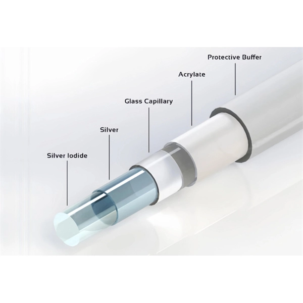
An optics expert explains how thin strands of glass that transmit light make modern telecommunications possible. Fiber-optic communication is a form of optical communication for transmitting information from one place to another by sending pulses of infrared or visible light through an optical fiber. The light is a form of carrier wave that is modulated to carry information. The fiber which is used for optical communication is waveguides made of. Understanding Fiber Optic Communication System: Working, Components, and Advantages The need for fast, high-capacity data transmission is on the rise, thanks to 5G technology, cloud computing, and a growing number of data-intensive applications. Thin strands of glass bundled in cables and stretched across continents and oceans make possible much of what we take for granted today, such as the Internet, Zoom calls, electronic. Fibers commonly used in optical communication are single mode and GI. Figure 4: Examples of light transmission through different optical fiber types Table 1. Optical Fiber Characteristics and Applications Optical signal rate attenuation as it passes through quartz fiber varies depending on a. Fiber optics is also the basis of the fiberscopes used in examining internal parts of the body (endoscopy) or inspecting the interiors of manufactured structural products. The basic medium of fiber optics is a hair-thin fiber that is.
[PDF]
Fibre Channel switches can be divided into two classes. These classes are not part of the standard, and the classification of every switch is a marketing decision of the manufacturer: Directors offer a high port-count in a modular (slot-based) chassis with no single point of failure (high availability).Switches are typically smaller, fixed-configuration (sometimes semi-modular), less redundant devices. OverviewFibre Channel (FC) is a high-speed data transfer protocol providing in-order, lossless delivery of raw block data. Fibre Channel is primarily used to connect to in (SAN) in co. When the technology was originally devised, it ran over optical fiber cables only and, as such, was called "Fiber Channel". Later, the ability to run over copper cabling was added to the specification. In order to avoid confu.
[PDF]
Can two switches with fiber ports be directly connected through fiber ports? The answer is yes. The connection between two or more Ethernet switches in a certain way (Uplink port, etc. ) is. Switch optical port intercommunication means that the optical fiber ports of two switches are connected to each other to achieve the purpose of network connection. Fiber optic technology is widely used in networking due to its high-speed data transmission capabilities and long-distance coverage. SFP transceiver modules almost always require two fiber optic cable strands. Fiber provides: Increased internet signal bandwidth. ) is called the cascade. Traditionally, network switches have been connected using copper cables, but with the increasing demand for high-speed and reliable connectivity, fiber optic cables have gained prominence. This article aims to provide a comprehensive understanding of how network switches are connected to fiber.
[PDF]
This report provides an in-depth analysis of the market for twine, cordage, rope and cables in Burkina Faso. Within it, you will discover the latest data on market trends and opportunities by country, consumption, production and price developments, as well as the. Market Forecast By Voltage (Low, Medium, High), By LV Installation (Overhead Conductors, Accessories), By Underground (PVC, XLPE, Terminations, Joints) And Competitive Landscape Do you also provide customisation in the market study? Yes, we provide customisation as per your requirements. As per Volza's Burkina Faso Import data, Cable import shipments in Burkina Faso stood at 4. 4K, imported by 343 Burkina Faso Importers from 209 Suppliers. The top 3 importers of Cable are India with 6,271,680 shipments. World Growth in percentage is 0. Burkina Faso, Service imports (BoP, current US$) is 1,450,112,792. As the chainplate is plated with chrome coatings, this steel cable carrier has a novel scientific design and is highly flexible in operation, easy in installation and uninstallation; 2. Since the drag chain is made of high-strength.
[PDF]