
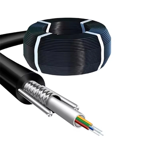
NEC-compliant grounding wire sizing calculator tool. Please enter a valid service size between 30 and 2000 amperes. The National Electrical Code (NEC) provides clear guidelines for ground wire sizing through Table 250. 122, but understanding how to apply these requirements correctly can make the difference between a safe installation and a costly code violation. Proper grounding conductor sizing is critical for. Calculate proper grounding wire sizes based on electrical system parameters. By fault current and length — considers potential short-circuit currents and conductor distance. By breaker size — quick lookup based on the installed breaker. NEC Ground Wire Size Chart provides standard wire sizing for grounding conductors in electrical systems. This chart is used to size the ground wire that runs with branch circuits and feeders. The second is the Grounding. AFL AlumaCore OPGW (Optical Ground Wire) is preferred for its central aluminum pipe and color-coded fiber optic buffer tubes which simplify the splicing process while providing optimum fiber protection as well as long term product reliability. Optical Ground Wire (OPGW) is a dual functioning cable.
[PDF]

This section applies to grounding of transmission and distribution lines and equipment for the purpose of protecting employees. Note to paragraph (a): This section covers. Correct grounding of services depends upon understanding the definition and role of the grounded conductor. The neutral conductor is typically the grounded conductor connected to the system's neutral point, carrying current under normal operation. Grounding electrode conductors must be connected at. Learn the grounding and bonding rules when powering two or more buildings or structures in the same area with a single service. To catch up on Lorenzo Mari's series on National Electrical Code 2023 Basics: Grounding and Bonding, follow these links: NEC's Section 250. Bonding is connecting things together with a conductive path to establish electrical continuity. Both are foundational safety concepts in the NEC, and. NFPA 70: National Electrical Code Article 250 covers the minimum requirements for grounding and bonding and, although the NEC lists requirements to abide by, it should not be taken as a design manual. Some terms and requirements discussed may be true for the European standards, however, the intent.
[PDF]
The following figure shows a typical breaker box panel for 120V and 240V circuits. There are three wires entering the main panel from the energy meter viz: 1. Hot 1 or Line 1 = Black Color 2. Hot 2 or Line.
[PDF]
When designing a cable tray wiring system, the designer should evaluate the National Electrical Code's (NEC) Equipment Grounding Conductor (EGC) options that are applicable for the project. Use the cable tray as the EGC. The metal in cable trays may be used as the EGC as per the limitations. Cable tray grounding wire is the safety connection that links your electrical system's cable tray to the ground. This provides a safe path for any stray electrical currents to flow safely into the earth, avoiding damage to your equipment and reducing the risk of electric shocks. It involves connecting cable trays to the facility's grounding system, providing a low-impedance path for fault currents and protecting personnel.
[PDF]
Fiber testing is the process of verifying the performance of optical fiber cabling. This process includes a range of tests and measurements such as insertion loss, optical return loss, and fiber length. It encompass.
[PDF]

As pluggable I/O data rates increase, the need to efectively limit EMI emissions and heat generated by fiber optic transceivers simultaneously arises. Typically this is done through an EMI containment vehicle such as a sheet metal cage or die cast housing. Legal status (The legal status is an assumption and is not a legal conclusion. Google has not performed a legal analysis and makes no representation as to the accuracy of the status listed. ) Current Assignee (The listed assignees may be inaccurate. In this guide, we will cover everything from what causes heat, to monitoring your SFP module temperatures in real. The developments introduced in the optical communication systems have been focused in 3 main objectives: increase of the propagation distance, increase of the transmission capacity (bitrate) and reduction of the deployment and operation costs. The achievement of these objectives was only possible. With the growing global deployment of Fiber-to-the-Home (FTTH) networks driven by the demand for ensuring high-capacity broadband services, mobile network operators (MNOs) face challenges of excessive energy consumption (EC) of wired optical access networks (OANs). This article will focus on I/O. Fiber optical transceiver is one of the key components of the fiber optic communication systems. The fiber optical transceiver modules convert electrical signal and optical signal to each other to exchange information.
[PDF]

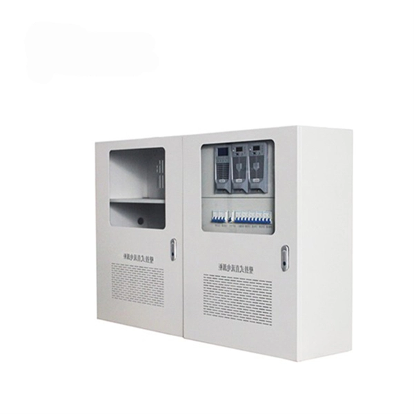
Within data centers, optical distribution boxes manage fiber connections between servers, switches, and storage devices. They enable high-density fiber management, reducing cable clutter and improving airflow. This use-case enhances data transfer speeds and system uptime. They protect delicate fiber cables from environmental factors like moisture, dust, and physical damage. These boxes are used in various settings, including outdoor street cabinets. Optical fiber distribution box (often referred to as optical fiber distribution box or ODF box) plays a crucial role in optical fiber networks, and its advantages are mainly reflected in the following aspects: First, efficient fiber management Modular design: The optical fiber distribution box. These boxes simplify network expansion and reduce installation complexity by combining fiber distribution and signal splitting functions in one enclosure. FDB is used for the purpose of distributing and terminal connection to numerous types of optical fiber systems. They are commonly used by FTTH clients wiring equipment, in order to provide protective connections. The box is compact, light and is widely used for end termination of villas and. An Optical Distribution Frame (ODF) is a specialized enclosure designed to manage, connect, protect, and distribute fiber optic cables in telecom and data networks. It acts as a central point for terminating, splicing, and distributing these cables, providing necessary protection and.
[PDF]
This guide covers the critical steps, from selecting the right electrical cable tray and performing accurate cable fill calculations to managing a safe cable pull through and ensuring all bonding and grounding requirements are met. Whether you're building a commercial setup or upgrading an industrial plant, proper cable tray installation ensures neat wiring, safe access, and easy maintenance. But before you lay the first tray or clamp down a single cable, you need a solid plan. This guide breaks down the process step by step. Several mounting. Installing a cable tray system requires careful planning to ensure it can support the weight of the cables and adheres to electrical safety codes. Here is a step-by-step guide on how to install a standard metal cable tray system (e., ladder or perforated type). When properly selected and installed, cable trays simplify routing, improve accessibility, and support future expansion while. Getting cable trays set up right and keeping them in good shape is vital. It stops issues, keeps things working, and saves you money over time. This guide will walk you through the key points for Cable Tray Installation and Maintenance, making sure your cable management systems are strong and.
[PDF]

Learn how to install a fiber optic termination box step-by-step for FTTH projects. Covers mounting, splicing, routing, labeling, and testing for indoor/outdoor use. Installing a fiber optic termination box is one of those jobs that looks simple on paper. A fiber termination box is the standard instrument used in fiber optic networks to connect, secure, and protect optical fibers at the terminating point. Proper installation and maintenance of FTBs are essential to ensure the reliability and performance of the network infrastructure. Before. FTTP or fiber To The Premises applications have reinforced the importance of reliable and stable fiber optic terminations. Good quality fiber laying and termination systems help achieve minimal back reflection and low signal loss. They also feature resistance to moisture, impact, chemical exposure. New pole mount bracket YK-SX, made by Jera line, to attach and reattach the fiber optic termination boxes, during aerial fiber deployment. No more time losses on reattaching the termination box from the pole. It serves as a critical junction point within a network, providing a centralized and secure. A Fiber Termination Box, also known as a Fiber Distribution Box, is a crucial component in fiber optic networks. FTBs play a vital role in ensuring the.
[PDF]
Step-by-step cable tray and conduit installation method with safety, quality and inspection procedures as per IEEE standards. But before you lay the first tray or clamp down a single cable, you need a solid plan. This guide breaks down the process step by step. Plan the Route Before You Drill No installation should start without a plan. Mark the cable tray route based on your electrical cable tray design and site. This guide covers the critical steps, from selecting the right electrical cable tray and performing accurate cable fill calculations to managing a safe cable pull through and ensuring all bonding and grounding requirements are met. For licensed electricians, mastering these principles is essential. This method statement describes a detailed procedure for properly installing cable trays and conduits for the Feeder System. The objective is to ensure safety, quality and compliance during the. Below is the detailed cable tray installation method statement not only for cable tray but also applicable for GI ladder and trunking for indoor and outdoor applications and in service rooms like pump rooms, electrical rooms and plant rooms etc. The Cable Tray system is installed in electrical rooms, plant rooms, and service corridors. The key requirements for cable tray installation include: Incorrect installation can lead to overheating, cable damage, or system failure. This is why proper planning and execution are.
[PDF]


