
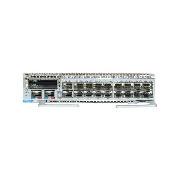
As pluggable I/O data rates increase, the need to efectively limit EMI emissions and heat generated by fiber optic transceivers simultaneously arises. Typically this is done through an EMI containment vehicle such as a sheet metal cage or die cast housing. Legal status (The legal status is an assumption and is not a legal conclusion. Google has not performed a legal analysis and makes no representation as to the accuracy of the status listed. ) Current Assignee (The listed assignees may be inaccurate. In this guide, we will cover everything from what causes heat, to monitoring your SFP module temperatures in real. The developments introduced in the optical communication systems have been focused in 3 main objectives: increase of the propagation distance, increase of the transmission capacity (bitrate) and reduction of the deployment and operation costs. The achievement of these objectives was only possible. With the growing global deployment of Fiber-to-the-Home (FTTH) networks driven by the demand for ensuring high-capacity broadband services, mobile network operators (MNOs) face challenges of excessive energy consumption (EC) of wired optical access networks (OANs). This article will focus on I/O. Fiber optical transceiver is one of the key components of the fiber optic communication systems. The fiber optical transceiver modules convert electrical signal and optical signal to each other to exchange information.
[PDF]
This comprehensive handbook will offer a completely updated and revised guide to lasers and laser systems, including the full range of their technical applications. Laser diodes offer high power for their size and produce electrical-power-efficient laser radiation. They consist of a p-n semiconductor junction, with a forward bias voltage applied to trigger a current through the junction. This induces population inversion (of electrons in the excited state) in. A diode laser, also known as a laser diode or semiconductor laser, is a compact electronic device that converts electrical energy directly into coherent light through the process of stimulated emission. The term “laser” is actually an acronym, standing for Light Amplification by Stimulated Emission of Radiation. The first volume outlines the fundamental components of lasers, their properties and working principles, with brand new chapters in. From telecommunications and data storage to medical surgery and 3D sensing, a laser diode is essential for barcode scanners, printers, and industrial cutting. The laser diode is an unsung hero of modern technology. Operational Mechanism: Laser diodes create light through stimulated emission within an optical cavity, with the light's properties influenced by the semiconductor.
[PDF]

Based on the need for real-time sag monitoring of Overhead Power Lines (OPL) for electricity transmission, this article presents the implementation of a hardware and software system for online monitoring of OPL cables. OptiSystem is an optical communication system simulation package for designing, testing, and optimizing virtually any type of optical link in the physical layer of a broad spectrum of optical networks, from analog video broadcasting systems to intercontinental backbones. A system-level simulator. Enhance your OTDR training and demonstrations with the portable Fiber Lab MSP. This all-in-one solution simulates P2P, FTTx, and Cell Tower fiber spans in a single unit, while including over 20km of fiber, good/bad splices, 1xN splitter, and reflective connectors. WHY CHOOSE THE FIBER LAB MSP? When. OCSim modules have been proven to provide accurate simulations. The modules which are continuously upgraded are and laboratory simulation experiments. The mathematical model based on differential equations and the methods of. This repository is a Python-based framework to simulate systems, subsystems, and components of fiber optic communication systems, for educational and research purposes. Several digital modulations available (M-PAM, square M-QAM, M-PSK, OOK) to simulate IM-DD and coherent optical systems.
[PDF]

Common methods of protecting busbars include overcurrent-based interlocking schemes, overcurrent-based differential protection, high-impedance differential protection, and percentage differential protection. Interlocking and overcurrent differential protection can be implemented with any suitable. DEFINITIONS. IV EXECUTIVE. Busbar Differential Protection Definition: Busbar differential protection is a scheme that quickly isolates faults by comparing currents entering and leaving the busbar using Kirchoff's current law. Current Differential Protection: This protection method connects CT secondaries in parallel and. Busbars play an important role in power transmission and distribution. They are employed as a central distribution point for all feeders. The problem is that the busbars. Busbars have typically been left without dedicated protection, from the following reasons: It is a fact that the risk of a short circuit happening on modern metal clad equipment is insignificant, but it cannot be completely dismissed. Nevertheless, the damage resulting from one short circuit may be. 25 kV insulation is required. These heat-shrinkable tubes for straight and bent busbars are extremely flexible, allowing them to be easily positioned on busbars and quickly instal ed using a gas torch or oven. They have a high expan-sion ratio, so each size of tubing fits a range of busbar sizes.
[PDF]
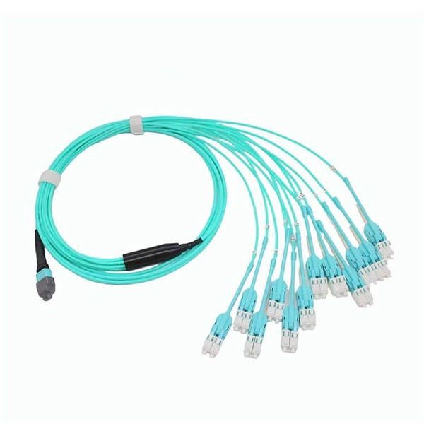
In practice, there are two main ways to terminate fiber optic cable: using a connector to join two fibers to create a temporary, removable joint, or using splicing technology to permanently join two bare fibers directly. Either. Terminating fiber optic cables essentially means putting connectors on fiber optic cable so that you can connect the cable to various devices or network components. Think of it as the equivalent of connecting the dots in a complex puzzle; without proper termination, the whole system can break down. Fiber optic networks are the backbone of modern communication systems, enabling high-speed data transfer and reliable connectivity. When deploying fiber optic cabling, one of the most critical decisions is how to terminate the fiber—either by splicing or using connectors. The process of fiber optic cable termination is the essential act of connecting fiber optic cables to devices, patch panels, or other cables to enable. This Applications Engineering Note explains how different optical fiber termination methods impact the optical performance of telecommunications systems. Optical fiber cabling systems support various communications technologies that use digital as well as analog signaling. This involves either installing a connector or creating a splice to establish a reliable connection point for the optical signal.
[PDF]
This guide covers the critical steps, from selecting the right electrical cable tray and performing accurate cable fill calculations to managing a safe cable pull through and ensuring all bonding and grounding requirements are met. Whether you're building a commercial setup or upgrading an industrial plant, proper cable tray installation ensures neat wiring, safe access, and easy maintenance. But before you lay the first tray or clamp down a single cable, you need a solid plan. This guide breaks down the process step by step. Several mounting. Installing a cable tray system requires careful planning to ensure it can support the weight of the cables and adheres to electrical safety codes. Here is a step-by-step guide on how to install a standard metal cable tray system (e., ladder or perforated type). When properly selected and installed, cable trays simplify routing, improve accessibility, and support future expansion while. Getting cable trays set up right and keeping them in good shape is vital. It stops issues, keeps things working, and saves you money over time. This guide will walk you through the key points for Cable Tray Installation and Maintenance, making sure your cable management systems are strong and.
[PDF]
Fiber testing is the process of verifying the performance of optical fiber cabling. This process includes a range of tests and measurements such as insertion loss, optical return loss, and fiber length. It encompass.
[PDF]
The PL-1000D simultaneously monitors up to 16 fiber strands, eight on the OTDR and eight on the OSA, and operates standalone over dark fiber, lighted fiber, or a third party network without impacting network traffic. The device monitors the entire D. The PL-1000D simultaneously monitors up to 16 fiber strands, eight on the OTDR and eight on the OSA, and operates standalone over dark fiber, lighted fiber, or a third party network without impacting network traffic. The device monitors the entire DWDM C-band spectrum and provides the optical spectrum, OSNR, and OTDR measurements of the fiber. The OTDR locates fiber cut by sending high powered optical pulses into the fiber and creating Rayleigh back-reflections. The returning signals are measured and calculated, indicating the accurate location and intensity of the fault. The OTDR supports GIS (Geographic Information System) using Rest API, enabling precise geographic location of disrupt. The OSA enables the user to monitor the OSNR and optical spectrum of each fiber and shows a full, accurate and detailed picture of the wavelengths used in the fiber. OSADiagram Graphical Display of the OSA, from PacketLight's LightWatch NMS Please contact usfor a quote or further assistance.
[PDF]

Based on analysis on the dispersion of the optical system of a MEMS-based VOA, we provide a method to reduce the WDL significantly with minor revision on the end-face angle of the collimating lens. 📦 For purchasing, use the RP Photonics Buyer's Guide for variable optical attenuators. It provides an expert-curated supplier directory, buyer-focused technical background information, and structured selection criteria to support professional procurement decisions. Variable optical attenuators are. An optical attenuator, or fiber optic attenuator, is a device used to reduce the power level of an optical signal, either in free space or in an optical fiber. The basic types of optical attenuators are fixed, step-wise variable, and continuously variable. Optical attenuators are commonly used in. Applications in broadband optical fiber communication system need variable optical attenuators (VOAs) with low wavelength-dependent loss (WDL). What Are Fiber Optic Attenuators? Fiber optic attenuators, also called optical attenuators, are passive. Optical attenuators are categorized based on their attenuation mechanism and adjustability: Fixed Optical Attenuators: These attenuators reduce the signal power by a predetermined value and are used in applications where a constant level of attenuation is required. It works by dissipating a portion of the optical power passing through it, thereby lowering the overall power level. Fiber optic attenuators.
[PDF]

This article covers various types of protective relays, such as overcurrent, directional, and differential relays, highlighting their operating characteristics and applications in electrical systems. Different Types of Protective Relays What is a Protective Relay?. Protective relays and devices have been developed over 100 years ago to provide “lastline”of defense for the electrical systems. They are intended to quickly identify a fault and isolate it so the balance of the system continue to run under normal conditions. The selection and applications of. Protective Relay Definition: A protective relay is an automatic device that senses abnormal conditions in electrical circuits and triggers actions to isolate faults. Types of Protective Relays: Protective relays are categorized by their mechanism (electromagnetic, static, mechanical) and function. A protective relay is an intelligent electrical device designed to detect faults in power systems and initiate corrective actions such as tripping a circuit breaker. : 4 The first protective relays were electromagnetic devices, relying on coils operating on moving parts to provide detection of abnormal operating conditions such as. Relion protection and control relays for several application reduce complexity.
[PDF]

Calculate US import duties, processing fees, and total landed costs. Powered by official USITC Harmonized Tariff Schedule data. Automatically applies additional. The Harmonized Tariff Schedule of the United States (HTS) sets out the tariff rates and statistical categories for all merchandise imported into the United States. This ad valorem duty stacks on existing Section 301 and Section 232 tariffs currently in effect. We will. The items concerned are referred to as the TL-SG108 desktop switch, the TL-SG1008PE desktop or rack-mountable switch, the TL-SG116E desktop or wall-mountable switch, the TL-SG1016DE desktop or rack-mountable network switch, and the TL-SG1016PE desktop or rack-mountable network switch. These. After Trump Tariffs Based on estimates from the Tax Foundation, Yale Budget Lab, and Penn Wharton Budget Model This US tariff calculator helps you estimate the cost of importing goods under the current Trump tariff regime. Whether you're importing from China, the EU, or anywhere else, use it to. Here's What That Means for Prices. Last updated 2 months ago. Our resources are updated regularly but please keep in mind that links, programs, policies, and contact information do change.
[PDF]

Porsche is improving the digital experience for the model year 2026 911, Taycan, Panamera and Cayenne model series. The revised Porsche Communication Management (PCM) system features more performance and offers access to the Porsche App Center. Communication Power System by Application (Wireless Access Network Base Station, Renewable Energy System, Internet Data Center, Core Network Center Room, Others), by Types (DC Power Supply, AC Power Supply), by North America (United States, Canada, Mexico), by South America (Brazil, Argentina, Rest. Tokyo – January 23, 2026 – NEC Corporation (NEC; TSE: 6701) today announced the development of a new Radio Unit (RU) for 5G Sub-6GHz band base stations, featuring Massive MIMO (*1) technology. You can find EDB at www. CPI is looking for passionate individuals to help shape the future through innovation and discovery. Job Opportunities » © 2026. In 2026, one theme is becoming increasingly clear: wireless power is evolving from a convenience feature into a foundational infrastructure layer for connected devices. What began as a wireless charging alternative is now shaping device architecture, user experience, and ecosystem design across.
[PDF]

Search results of Top 14 Cabling and Fibre Optics Companies in New Zealand. Listings are verified with accurate business information. LAN Cabling Products Limited (LCP) specializes in telecommunications and has a strong emphasis on fiber optic connectivity, representing major brands in the industry. Their experience and distribution network in New Zealand and the Pacific Islands position them as a key player in advanced data. OplinX New Zealand Limited specialises in supplying high quality fibre optic cabling products into the data and telecommunication market. Oplinx NZ has been established as a competitive contender to lead the optical market with strategic innovation and customer focussed pro-activity. With over 40 years of industry experience, Maser is a trusted provider of advanced technology solutions, sourced from our network of leading international suppliers across the telecommunications, enterprise, industrial and defence sectors. Our business is comprised of 4 key service streams. There are 9 Fiber optic products suppliers in New Zealand. Notably, Auckland accounts for approximately 44. 44% of all Fiber optic.
[PDF]
