
Find location, phone number, services, reviews and more. Your source for comprehensive Enterprise Network Cabling and Fiber Optic Solutions. © 2024 CB Cabling Technologies Ltd. ) has been established since 2004, however our team has over 10 years' experience in the networking industry. voice and data, fibre-optic solutions, design and construction of server rooms and the installation, distribution and servicing of. Make a Payment We provide High Quality Products & excellent customer service to our clients. + (876) 618-6790. Optical cable tray is a system designed to protect and route fiber optic patch cords, cable assemblies to and from network cabinets, ODF and other terminal devices. Ducting offers ideal solutions for optical raceway requirements and application with pleasing appearance and easy maintenance. l. CB Cabling Technologies Ltd 24 Half Way Tree Road - Kingston Phone: +1 876-906-3284 CB Cabling Technologies Limited (formerly CB Cabling Ltd. ) is a wholly owned Jamaican company which has been in existence since 2004. Our. and Justice (OP1201). The project is consistent with the 2016-2021 IDBG Country Strategy with Jamaica (GN2868) and will contribute to the Corporate Results Framework (CRF) 2016-2019 (GN-2727-6) output indicators of: (i) Government agencies benefited by projects that strengthen technological and.
[PDF]
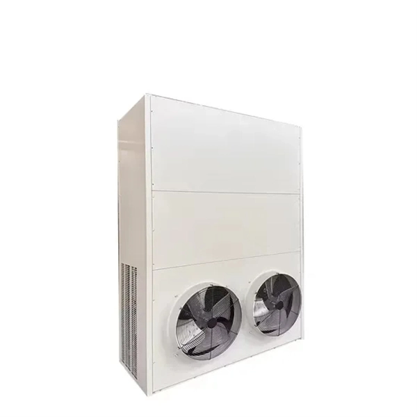
The SmartAisle offering optimizes infrastructure deployment and management with an intelligent row-based system that integrates data center racks, power, row cooling, aisle containment, monitoring and control technologies for spaces with up to 40 racks. The Swedish market for Cold Aisle Containment (CAC) systems represents a critical and sophisticated segment within the nation's broader data center infrastructure landscape. Characterized by a strong emphasis on energy efficiency, sustainability, and technological innovation, the market is driven. Ardmac have developed a range of Ground Supported (GS) and Ceiling Supported (CS) assemblies catering to an array of different modular clean rooms and off-site construction industry requirements including data centre design and data centre construction. Structural ceiling grids support the. Complete aisle containment solutions and cooling systems for hot and cold air separation. Optimizing the air flow in your POD and data center has several benefits, including reducing energy costs and improving efficiency. It maximizes the system's efficiency, minimizes its power consumption, and reduces its footprint, making it the perfect solution for medium- to. To increase the "Energy Efficiency" and manage the "Physical Security & Access Control" in data center environments, KabinPLUS offers Data Center Aisle and Containment Solutions.
[PDF]

Chile, in partnership with Google, is launching the Humboldt Cable System, the first fiber-optic submarine cable connecting South America with Asia and Oceania. As of 2025, the plan is to build a 14,800-kilometre (9,200 mi) cable from Valparaiso, Chile, to. The Humboldt Cable System is a 14810 km submarine cable connecting Chile, French Polynesia and Australia, with branches for the possible connection of other countries and territories. Stretching about 15,000 kilometers, it will connect Valparaiso, Chile, to Sydney, Australia, and then extend to Asia. Developed with H2. The company specializes in advanced fiber optic telecommunications and is dedicated to deploying fiber optic networks throughout Chile, enhancing broadband access for consumers and businesses. Their extensive ultra-broadband network, built to high industry standards, supports the digitalization. Google and the Chilean government have signed an agreement to install the Chile Submarine Humboldt Cable, a 14,800 km undersea fiber-optic line linking Valparaíso, Chile, with Sydney via French Polynesia. Slated for completion by 2027, it will be the first-ever direct South Pacific cable.
[PDF]
Our engineered protective building solutions comply with current editions of IBC, UBC, SBC, BOCA, NEC, ACI 318-95 and AISC in addition to achieving and sustaining the structural integrity for Category 5 scenarios resulting in a 150 mph wind loading capacity. Experience unparalleled protection and reliability with Enviro Buildings ® telecom shelters, specially designed for ground site applications in challenging environments. Our insulated shelters are engineered to withstand extreme temperatures, ensuring optimal performance in both high and low. Module X Solutions designs, engineers and manufactures modular and build on site precast or lightweight steel telecommunication equipment shelters to industry and client specific requirements. We design and manufacture telecom shelters for electrical equipment for all purposes. Airport ICAO shelters, telecommunication shelters, GSM shelters, equipment containers, server rooms, VAR (Video. “Technical Shelters” are structures designed for housing and protecting electronics and power equipment, commonly used in telecommunication base stations and remote switching centers. Our shelters can be shipped nationwide. Many models can be easily assembled and transported to remote locations using our skid mounts. The shelters are constructed from hot-dipped galvanized metal, coated with a durable finish that won't.
[PDF]

Powered by Al-driven algorithms, it automatically analvzes end-face imperfections, making it a critical tool for ensuring the reliability of CPO systems-supporting eficient data center operations and smarter future network infrastructure. • Additional connections for foot activation pedal & backplane handset extension. CleanBlastPRO™ is VIAVI's newest automated fiber end-face cleaning system, designed for seamless deployment by component and connectivity manufacturers and integrators. It ensures clean fiber connectors across. AFL offers a complete selection of compact fiber optic cleaning kits for field cleaning of connector end-faces and splicer v-grooves. We offer pre-stocked kits with a variety of cleaning tools and can also build you custom kits to meet your specific application needs. With a variety of kit options. Fiber connectors are precision components designed to carry light signals with minimal loss. Any debris, residue, or static can: Scatter or block light, leading to insertion loss. Create back reflections, which degrade signal quality. Scratch or pit the end face, causing permanent damage. Its large-field-of-view (FOV)design ensures full-core coverage in a single scan, while ultra-high-resolution optics accurately detect micron-level defects. Automated cleaners use a high-speed air/fluid mixture to flush contaminants from the endface, ensuring thorough, consistent cleaning. Fiber-optic technology has become the.
[PDF]

This infographic summarizes results from simulations that demonstrate the ability of Congo to match all-purpose end-use energy demand with wind-water-solar (WWS) electricity and heat supply, storage, and demand response continuously every 30 seconds for three years (2050-2052). JNTech is pleased to announce the recent successful completion of a remote area microgrid project in the Democratic Republic of Congo (DRC). The micro-store network project is a photovoltaic (PV) power station designed to provide stable and sustainable power to local communities and villages. As a. This Environmental and Social Management Plan (ESMP) has been prepared for the project “Operationalization of the Oyo Centre of Excellence for Renewable Energy and Energy Efficiency in the Republic of the Congo” (Project ID 190379). All-purpose energy. More than 180,000 people and businesses are expected to benefit from first-time access to electricity or an improved connection through the roll out of a 13. 7MWp portfolio of solar-hybrid isolated grids in DRC. REPP has invested USD 6 million to support the development and construction of a 13.
[PDF]

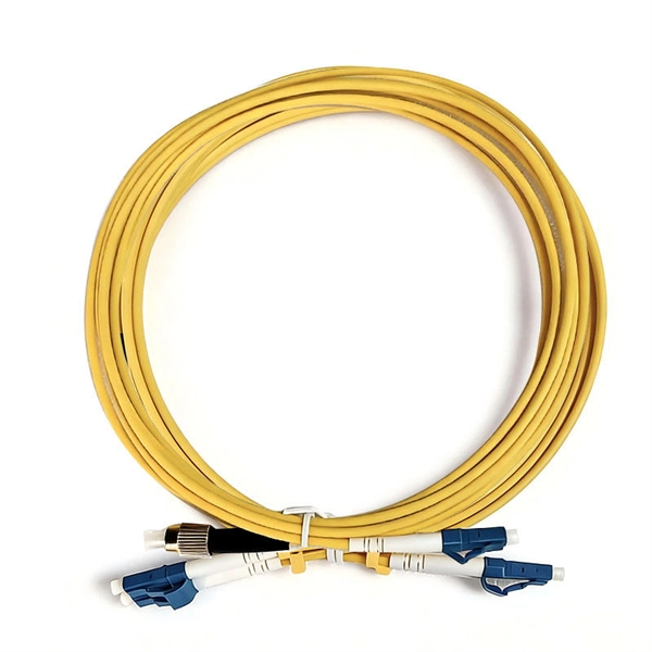
Home and business fiber optics projects typically range from a few hundred to several thousand dollars, depending on run length, fiber type, and labor needs. The main cost drivers are materials, installation time, and environmental factors that affect trenching, conduit, and terminations. Commercial building installations with 100-200 network drops generally range from $15,000 to $30,000. Single-mode fiber costs less per foot than multimode fiber, but it requires more. What is Fiber optic network design? Fiber optic network design involves the planning, routing, and drafting of Fiber cable layouts to support high-speed data transmission. It includes detailed mapping of backbone, distribution, and drop connections for FTTH, FTTP, FTTx, and enterprise networks. Fiber optic network design refers to the specialized processes leading to a successful installation and operation of a fiber optic network. It includes first determining the type of communication system (s) which will be carried over the network, the geographic layout (premises, campus, outside. According to ResearchAndMarkets, the global market for fiber optics was estimated at $5. 8 billion in 2022 and is expected to reach $11. This is the dominant broadband access technology across half of OECD countries today. The price landscape varies from basic drop cables to enterprise backbone runs, with per foot and per reel pricing common in estimates. This guide presents cost ranges.
[PDF]
Discover AZE's advanced All-in-One Energy Storage Cabinet and BESS Cabinets – modular, scalable, and safe energy storage solutions. Featuring lithium-ion batteries, integrated thermal management, and smart BMS technology, these cabinets are perfect for grid-tied, off-grid, and. rgy storage technology has become a key pillar in building new-generation power systems. It is being widely deployed across grid peak-shaving, me retardancy, non-toxicity, RoHS/R foam, addressing the dual needs of noise and thermal control in energy storage systems. This solution has been. Relying on its cutting-edge clean power conversion technology, industry-leading battery technologyand grid forming technology, Sungrow focuses on integrated energy storage systemsolutions. The core components of these systems include PCS, lithium-ion batteries and energy management systems. But hold onto your solar panels, because this Middle Eastern gem is quietly becoming a laboratory for energy storage innovation. From government officials sweating over. Energy experts have lauded the Cabinet's recent approval of a grid-scale battery energy storage system (BESS) for the National Electric Power Company's transmission. Hybrid Solar-Geothermal Heat Pump Systems: Simulated for various Jordanian locations, these systems incorporate storage to optimize.
[PDF]

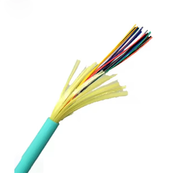
Fiber optic network diagrams represent the architecture and connectivity of fiber optic systems, and their design philosophy integrates technical, functional, and conceptual aspects. The diagrams abstract complex details of fiber optic systems to make them. Fiber optic network design refers to the specialized processes leading to a successful installation and operation of a fiber optic network. It includes first determining the type of communication system (s) which will be carried over the network, the geographic layout (premises, campus, outside. A fiber optics network diagram illustrates how high-speed data travels from an internet service provider to end users. These diagrams help engineers plan infrastructure for residential and commercial buildings. What is fibre network mapping? Fibre network mapping is a critical process in the planning, deployment, and management of fibre optic networks. I'm needing symbols for common fiber optic components, cables, connectors, backbone ports, etc. Can anyone help me out? Some examples of a diagram would also help. 10-27-2018 01:41 AM Do you know if there's some symbol standard. Definition: Fiber optic cable is also called the “ Optical Fiber Cable “, and it is simply Ethernet networking cable that contains the multiple optic fibers, and they allow to transmit data with massive volume. Main goal of designing the optical fiber cable is to offer ultra performance data.
[PDF]

In this video, we'll walk you through the process of wiring a home distribution box with a detailed connection diagram. In this article, we will delve into the details of an electrical sub panel diagram, discussing the various components, their functions, and the proper wiring techniques. Whether you are a homeowner tackling a DIY electrical project or an electrician looking to expand your knowledge, this guide will. A 30-amp sub panel functions as a secondary electrical distribution point, receiving power from the main service panel to serve a localized area. This small panel is commonly used to provide lighting and receptacle power to detached structures like a garage, a workshop, or a small shed. more Welcome to our channel! In this video. Load Calculation: Perform a load calculation to determine the total electrical load of the building. This involves calculating the power requirements of each individual device or system and adding them together to get the total load. It is important to ensure that the wiring and subpanel can handle. An electrical panel box, also known as a breaker box or a distribution board, is a crucial component of any electrical system. It serves as a central hub for distributing electricity throughout a building, ensuring that power is delivered safely and efficiently to all the required locations. ) is a cabinet or cutout box which contains on controlling and protective devices (such as circuit breakers, fuses, switches etc.
[PDF]

In this guide, you'll learn how to create rack diagrams that are accurate, scalable, and easy to maintain—so you can plan smarter, troubleshoot faster, and keep your infrastructure organized. This guide will explore the cost breakdown for rack and stack solutions, factors that influence pricing, and how companies can optimize their setup costs for maximum efficiency. Additionally, we will take a closer look at Digital Infotech Solutions, a leader in providing custom rack and stack. Most data center colocation providers hide pricing behind request-for-quote (RFQ) processes. You contact them, wait three to five business days, and only then learn whether colocation fits your budget. This opacity makes it nearly impossible to benchmark costs, negotiate terms, or plan. Whether you're planning a new deployment, reorganizing a rack, or documenting existing infrastructure, a clear visual layout keeps everyone aligned and prevents costly mistakes. Visit our free and simple network rack planning tool to create and export your rack. No registration or download required. Just follow this link and start designing in our pre-designed Server Rack Diagram Template. Before you. A rack diagram is a two-dimensional elevation drawing showing the organization of specific equipment on a rack. It provides a clear overview of the physical layout of the rack, including the placement and positioning of servers, switches, storage devices, and other.
[PDF]
Engineers involved in the design, characterization and validation of Universal Serial Bus Revision 2.0 (USB 2.0) devices face pressure to speed new products to market. Tools are available to help them quickl.
[PDF]

This AutoCAD DWG file includes a complete Single Line Diagram (SLD) of a Distribution Board, showing circuit breakers, wiring connections, and load distribution for lighting, power, and mechanical systems. Distribution box The system diagram usually shows the electrical connection and configuration inside the distribution box in a graphical way, including busbars, circuit breakers, fuses, load devices and other elements. In practical applications, the corresponding system diagram can be drawn. An Electrical Distribution Board (DB) is an essential component of any electrical system — it receives power from the Main Distribution Board (MDB) and distributes it to various sub-circuits or equipment. Power supply is received from LT panel and distributed to the outgoing feeders for utilization. Understand its role in electrical systems and safety. Inside. The distribution box (DB box) helps safely and efficiently distribute electrical power. But what exactly is a power distribution box, and why is it so essential in our daily lives? The DB panel board controls the flow of electricity. Wiring diagram shows both PNP and NPN wiring. Actual units use PNP status indicator, NPN status indicator, or neither. Dimensions are shown in mm (in. 40 ft)] or 10 [10 m (32.
[PDF]
