
View 18 Communications Equipment Manufacturing company profiles below. There are 88 Telecommunications equipment suppliers in Bolivia as of November, 2025. **** Huawei Technologies. ****. Find detailed information on Communications Equipment Manufacturing companies in Bolivia, including financial statements, sales and marketing contacts, top competitors, and firmographic insights. 06% increase from 2023. 02% of all Telecommunications equipment suppliers in Bolivia are single-owner operations, while the. Market Forecast By Component (Fiber, Transceiver, Switch, Splitters, Circulators), By Technology (SONET/SDH, WDM, CWDM, DWDM, Fiber Channel), By Application (TELECOM, Data Center, Enterprise), By Data Rate (Up To 40 GBPS, Greater Than 40 Gbps To 100 Gbps, Greater Than 100 Gbps), By Vertical (BFSI. Communication Equipment NETWORKS: 1 pc. Seair is proud to have a loyal customer base from big brands. Explore verified Communication importers in Bolivia with customs shipment details, buyers list, and trade data reports for smarter import-export decisions.
[PDF]
BARCELONA, Spain, March 6, 2025 /PRNewswire/ — At the Mobile World Congress 2025 (MWC 2025), Huawei launched the StarryLink optical modules, designed to enhance network experiences with “3S” quality (Spanning, Stable, Secure). This announcement occurred during the data center session titled. The global optical transport market returned to growth mode in 2025, climbing 10% year over year to reach $16 billion, according to new data from Dell'Oro Group. The market, projected to reach $14. 7 billion in 2025, is forecast to.
[PDF]
The communication system of fiber optics is well understood by studying the parts and sections of it. The major elements of an optical fiber communication system are shown in the following figure. The ba.
[PDF]

This paper will review the development of fiber-optic high-temperature sensors over the last 30 years, presenting their design and fabrication methods according to sensing type and typical temperature measurement performance. The full paper consists of eight sections. Fiber-optic high-temperature sensors are gradually replacing traditional electronic sensors due to their small size, resistance to electromagnetic interference, remote detection, multiplexing, and distributed measurement advantages. This paper reviews the sensing principle, structural design, and. Luna's Optical Backscatter Reflectometer (OBR) products are based on OFDR and provide a level of detail and precision not available with the prevailing fiber optic diagnostic tool - the optical time domain reflectometer (OTDR). OBR systems map out loss along a single-mode fiber (SMF) or multi-mode. breadth and most comprehensive solutions for optical communications test products to be found in one place. Corning's High Temperature Fibers are designed for applications requiring improved fatigue resistance, high usable strength, and excellent resistance to higher temperatures and hydrogen permeation. Thus, wireless communication -situ processing of data would combined with in significantly improve the ability to include sensors into high temperature systems and thus lead toward more intelligent engine systems. NASA Glenn Research Center (GRC) is presently lea, communication systems,ding the.
[PDF]

Also, please take a look at the list of 44 communication cable manufacturers and their company rankings. Quabbin Wire & Cable Co. *Including some distributors, etc. On the Thomas Network, you'll find more than 3200 suppliers of cables in the US. You can filter these companies by location, certifications, and more factors to easily find and connect with the right supplier for your needs. We've listed the most frequently sourced cable suppliers below: Philatron. This section provides an overview for communication cables as well as their applications and principles. Dacon Systems. From Fiber Optic to Copper Cables, from the most innovative products to the smartest solutions, from industries such as Broadcast or Enterprise to Industrial or Data Center, OCC has the connections you need. We have the resources, innovative technology and industry expertise to meet the growing needs of customers around the corner and around the world. Whatever the application, our in-house engineering team of compound, process and. NAI is a global leader in the manufacturing of advanced high-reliability connectivity solutions for mission critical and other high-performance applications. Our world class integrated supply chain and operations management, combined with a global footprint in lower cost regions, provide our. Browse our broad range of connectivity products designed to help enable your communication networks. Easily create a bill of materials list.
[PDF]

Urban Areas: 25–40m spacing (concrete poles, 10–12m height)., steel lattice structures). Factors: Cable weight (kg/km) Ice loading (up to 50mm. The Fiber Optic Association, Inc. (FOA) was founded in 1995 to help develop the workforce to build the fiber optic networks to support a rapid expansion in communications and the Internet. The charter of the FOA was to promote professionalism in fiber optics through education, certification, and. to n utral comm. cable R. FO-CS JOINT USE CLIMBING SPACE REQUIREMENTS 51. APPENDIX A - COVER SHEET / TOC 52. RUS DRAWING #PM12 58. CHECK. d suppliers of electrical construction services. They define a minimum baseline of quality and workmanshi for installing electrical products and systems. NEIS® are intended to be referenced in contrac documents for electrical construction ation or liability to users of this publication. Choose the type of pole The basic pole height is 7m and the tip diameter is 150mm. In case of special sections, crossing obstacles or roads or railways, the pole height of 8m, 9m, etc. can be selected. Cables 300 V or less need to be a minimum two feet over the street light. Climbing Space is an unobstructed, vertical space along the side or corner of the pole. In gen-eral, it consists of an imaginary box, 30-inches square, extending at least 40 inches above the highest communications cable or.
[PDF]
An optical line termination (OLT), also called an optical line terminal, is a device which serves as the service provider endpoint of a passive optical network. It provides two main functions: to perform conversion between the electrical signals used by the service provider's equipment and the fiber optic signals used by the passive optical network.to coordinate the multiplexing between the conversion. FeaturesOLTs include the following features: • A downstream frame processing means for receiving and churning an cell to generate a downstream frame, and converting a parallel dat. Most vendors integrate an entire fiber optic management system for ISPs to manage OLTs as well as client ONTs and as such are not interoperable. • • BT-PON.
[PDF]
These systems work together to achieve the correct balance of temperature, which affects glass viscosity, and draw “tension. ” Other subsystems are instrumental in avoiding vibration and in assuring the bare fiber is not exposed to dust, moisture, and other contaminants. Legal status (The legal status is an assumption and is not a legal conclusion. Google has not performed a legal analysis and makes no representation as to the accuracy of the status listed. ) Current Assignee (The listed assignees may be inaccurate. Two primary processes exist: cold fill and hot fill. Understanding their differences helps manufacturers make informed decisions. Cold Fill: Room Temperature. Optical fibres in a cable are normally protected in one of two ways, either being tight buffered or contained in loose tubes. Fiber is drawn vertically. Step 1: Preparing the Raw Material – Silica The first stage in making a fiber optic cable begins with the raw material: silica (silicon dioxide). Silica is chosen because of its purity and ability to transmit light efficiently with very little loss. The silica is refined and shaped into large. An annealing furnace design has been proposed to lower the attenuation of optical fiber by lowering its fictive temperature during the fiber draw process. The fictive temperature of Germania-doped single mode o fiber lies in the range of 1150~1300 C and this can be tailored by controlling the.
[PDF]
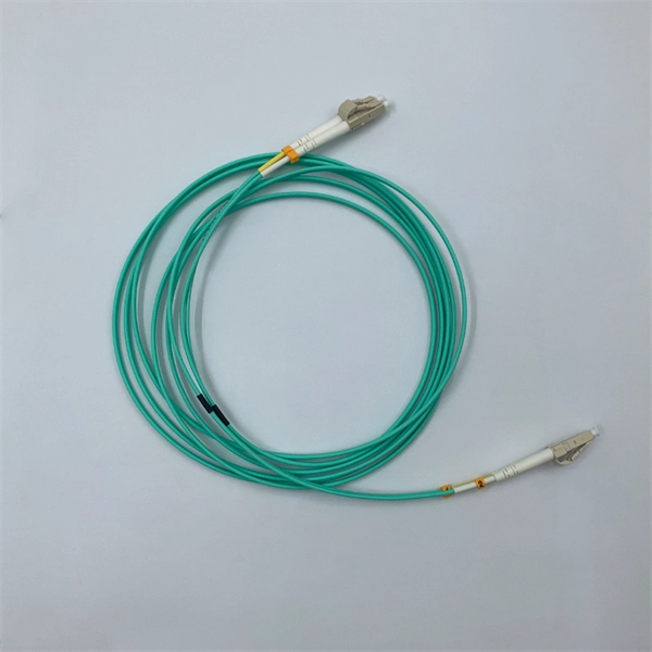
Assembled with Corning 50/125um, laser optimized, Wideband Multimode Fiber (WB-MMF) and comes pre-terminated with duplex LC to LC connectors. OFNR riser rated, lime green, zip-cord reinforced, 2., flame retardant, water resistant and UV resistant jacket. FS offers OM5 multimode fiber patch cables 50/125 with full use of shortwave wavelength division multiplexing (SWDM) tech for 40G/100G cablings, 100% optically tested. Corning® ClearCurve® OM5 wide band optical. ShowMeCables offers MPO/MTP fiber cables. Stock cables range from 1 meter (3. Our MPO/MTP fiber cables are either MPO to MPO no pins or MPO to MPO with pins and number of fibers are 8, 12 and 24. Mode types include OM3 and OM4 and genders are male-male and. L-com provides a wide variety of fiber optic cables in multiple configurations. We offer specialized fiber optic cable assemblies in single mode or multimode and simplex or duplex optic cables featuring ST, SC, FC, LC, MTRJ, and MU-style fiber connectors. 0mm outer LSZH (Low Smoke Zero Halogen) jacket, an even safer alternative to only OFNR riser rated cables. This significantly increases data capacity without.
[PDF]

An optical module is mainly composed of optoelectronic devices (including the optical transmitter and optical receiver), functional circuitry, and optical interfaces. Its fundamental role is to bridge the gap between electrical equipment and optical fibers. Optical modules are key components in fiber optic communication systems, responsible for electro-optical conversion, meaning the conversion of electrical signals to optical signals or vice versa. The internal structure of an optical module is complex but can be divided into several main parts. As an essential component of optical fiber communication, optical modules are optoelectronic devices that facilitate the conversion between optical and electrical signals during the transmission process. Operating at the physical layer of the OSI model, optical modules are core devices in optical. This comprehensive guide breaks down the internal structure, core components (TOSA, ROSA, lasers), and operational mechanisms of SFP optical modules, enriched with technical insights and real-world applications. It is available in TO-CAN, Gold-BOX, COC (chip on chip), COB (chip on board), and other packaging forms. This article will introduce you to the.
[PDF]

TendersOnTime, the best online tenders portal, provides latest Namibia Optical Fibre tenders, RFP, Bids and eprocurement notices from various states and counties in Namibia. Thank you for visiting Swanib Namibia! To find the solution for your electrical needs, visit our Products or Services page. Swanib Cables, a distributor of electric cables, transformers and fibre optic cables to the Namibian mining, utilities / infrastructure and telecom sectors has been a market. Within the team, a combined 31 years' experience in Construction, Civils, and Fibre Optics. com offers an unmatched database of Optical Fibre Cables tenders from Namibia, more than any other platform. Daily, new procurement. Use this hollow-core fibers buying guide to compare major types, define selection criteria, and find suppliers: Professional purchasing of high-value photonics products is a substantial responsibility, where a structured decision-making process is essential. RP Photonics offers a lot of help: Get. Oryx Fibre Infrastructure is an open access fibre optic network provider in Namibia that owns and operates long distance (backhaul and long haul) fibre infrastructure. We own our secure transmission and backbone fibre infrastructure and provide connectivity services to telecommunications operators.
[PDF]
An optical transceiver module, often simply called an optical module, acts as a signal conversion interface in fiber optic networks. It transforms high volumes of electrical signals into optical signals for transmission over fiber cables, or reverses the process at the receiving. As an essential component of optical fiber communication, optical modules are optoelectronic devices that facilitate the conversion between optical and electrical signals during the transmission process. Operating at the physical layer of the OSI model, optical modules are core devices in optical. An optical module is a typically hot-pluggable optical transceiver used in high-bandwidth data communications applications. Its primary function is to achieve optoelectronic conversion by converting electrical signals into optical signals and vice versa. If you're dealing with data centers, telecommunications, or AI networking, grasping the key parameters of an optical. What is an Optical Module? The Ultimate Guide to Principles, Types, and Troubleshooting Optical Modules (also known as Optical Transceivers) are critical components in fiber optic communication systems. Among various optical module form factors, SFP (Small Form-Factor Pluggable).
[PDF]
Multimode fiber optic cable has a larger core, typically 50 or 62. 5 microns that enables multiple light modes to be propagated. Because of this, more data can pass through the multimode fiber core at a given time. The maximum transmission distance for MMF cable is around 550m at the speed of. Multimode Fiber (MMF) has a core diameter, typically 50–100 micrometers, has ability to transfer multiple modes of light through the fiber core, uses lower-cost electronics (LED, VCSEL) operates at the 850 nm and 1300 nm wavelength and is used for short distance interconnections (up to 550m). This Applications Engineering Note (AE Note) discusses the criteria for properly selecting the optimal multimode fiber (MMF) for enterprise applications. Both fiber types play essential roles in today's optical.
[PDF]


