
How to Install a Fibre Connector into a Patch Panel (Easy fibre optic connector installation) How to Install a Fibre Connector into a Fibre Optic Patch Panel. How do you install fibre optic connectors?. Connecting a fiber patch panel to a switch is a critical step in setting up a fiber optic network. There are different types of connectors. In today's high-performance networks, fiber optic patch cables are the lifelines that ensure smooth data flow across switches, servers, and routers. Even the most advanced optical transceivers can only perform at their peak when paired with properly installed, clean, and precisely managed fiber. Choose an SFP module based on the fiber optic cabling that will be connected to the network switches. SFP transceiver modules almost always require two fiber optic cable strands. A Fiber Patch cord connects two devices. You plug it into a switch, router, or patch panel. It's ready to use out of the box. A pigtail is for splicing. You fuse it to a. With a railroad switch (patch panel), the train (data) can travel from A to B, C and even more destinations, otherwise it can only go from A to B, or C to D. This article, What Is a Patch Panel Used for?, has explained it thoroughly.
[PDF]

This cable must then plug into the dedicated Internet or Wide Area Network (WAN) port on your router. The WAN port is often clearly labeled and colored differently, as it is designed to receive the external internet feed. To connect your fiber optic cable to a router, ensure you have the following: Fiber optic modem (ONT): Most fiber connections require an Optical Network Terminal (ONT), provided by your ISP. This. The fiber optic cable does not plug directly into a standard home router because the signal type must be translated. The fiber line terminates at the Optical Network Terminal (ONT), which is typically supplied and installed by the internet service provider. This specialized equipment serves as the. This usually involves connecting the fiber cable from your internet service provider (ISP) to your home network equipment. It might be labeled "Fiber," "FTTH," "PON," or have a small receptacle for the fiber connector. Here's a simple guide to help you through the process: 1. Check Your Fiber Optic Equipment Before you start, make sure you have the necessary equipment: Fiber Optic Modem (ONT – Optical Network Terminal):. That is a router, put it in bridge mode if you want to plug your own in and not worry about double NAT Search the model # and figure it out Blue is 5gbps and yellow are probably 1gbps. How much bandwidth does your router need? Do you anticipate more than 1g going through? If so blue.
[PDF]

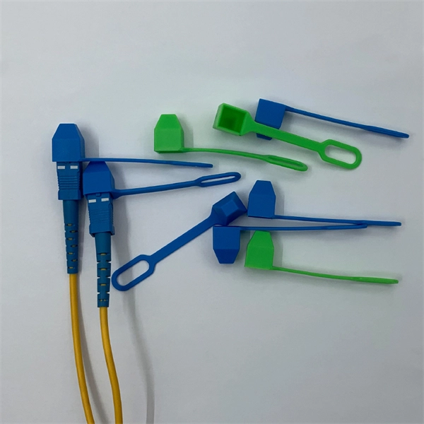
This video goes over common types of connectors, their respective adapters, and how to properly connect and disconnect them. more Are you interested in seeing how fiber optic connectors get. Unplugging a fiber jack, also known as a fiber optic connector, is a delicate process that requires attention to detail and proper handling to ensure the integrity of the fiber optic cables and connectors. Fiber optics are used in a variety of applications, including telecommunications, internet. If you're wondering how to remove fiber optic cable from connectors, there are a few different ways to do it. You need to know which connector is the correct one for the cable and what kind of wire it's made of. You can also use shears or wire cutters to cut through the connector. This article. Fiber optic connectors are essential components in fiber optic networks, providing a reliable connection between cables and equipment. Removing these connectors requires care to avoid damaging the delicate fibers or the connector itself. To connect a fiber optic cable to SFP optical module, first ensure the SFP is fully inserted into the network port until it "clicks", then remove the dust caps from both the SFP and the LC fiber optic connector.
[PDF]

Learn how to splice fiber optic cable using fusion splicing with this complete step-by-step guide. Includes tools, best practices, loss standards (ITU-T G. 652), cost analysis, and FAQs for network engineers and installers. Splicing fiber optic cable is an extremely important phase for making dependable, high-speed communication infrastructures. Regardless of the type of fiber network you're deploying, be it for telecom, enterprise data centers, or smart city infrastructure, fusion splicing provides the benefits of. This is where fiber optic cable splicing—the process of creating a permanent, high-performance join between two fiber ends—becomes critical. For network managers and technicians, a poor splice can lead to significant signal degradation, network downtime, and costly troubleshooting. At Turn-Key. Think of a fiber optic cable splice as the seamless stitching that keeps data flowing through the delicate threads of a network—like a master tailor joining fabric with precision. What is Fiber Optic Splicing and Why is it Needed? – #1. Discover how to efficiently use sleeves and the heat. The answer lies in splicing, both fusion and mechanical. In this comprehensive guide, we will delve into when.
[PDF]

Choose from our selection of routing rings and hooks, loop clamps, hangers for pipe, tube, and conduit, and more. Same and Next Day Delivery. Our Fiber Optic Mounting Hardware category includes essential components designed to secure, organize, and protect fiber optic cables and equipment. Proper mounting hardware is crucial for efficient cable management, strain relief, and long-term network stability. Whether you need to mount cables. We at Primus Cable understand the validity of overhead cable management as an additional means of keeping networking cables organized and safely out of the way. Through our extended. We supply Doc's Industries superior J-Hooks to provide cable support for all data communication and low voltage cables; for a variety of trades and uses, such as telecom, electrical, fibre optic, CAT5, voice/data cables and fire protection cabling. The cable hooks are very sturdy and easy to. J hooks and bridle rings are designed specifically for hanging cables in ceilings and rafters. J hooks can be used for category 5E and category 6 cables without putting undo stress on these cables. We now have J Hook Trees in 1 5/16", 2" and 4". These unique J Hooks make it easier to have multiple. Hot dip, dacromet or chroming galvanization, prevent from oxidation and corrosion. Through our extended.
[PDF]

One SFP module is inserted into the switch's SFP port, and another module is inserted into the SFP port of the target device, facilitating data transmission through the fiber optic cable. SFP ports are small hot-pluggable module interfaces typically used for connecting fiber optics or copper cables. They support various transmission rates and distances, including 1G, 10G, and higher speeds. SFP modules can be selected based on the requirements, whether it's single-mode fiber for. An SFP port is a physically small slot in a networking device that accepts an SFP module insert. Most modern networking devices, such as Ethernet switches, servers, routers, network interface cards, and fiber media converters, generally have two or more built-in SFP ports. You may connect different. In plain terms, an SFP port on a gigabit switch is the little plug-in hole that gives the switch physical flexibility — the ability to use fiber one minute and copper the next without buying a different switch. Unlike fixed RJ45 copper ports, SFP ports support both fiber and copper modules, enabling far longer distances, greater flexibility, and improved scalability in enterprise. First, to connect SFP modules with fiber optic cables, ensure that the module type matches the line, as there are different modules for single-mode and multimode fiber. Next, insert the module firmly and securely into the SFP port, then attach the cable to the module using the connector. Switches with SFP ports can.
[PDF]

Optical fiber cables consist of several key components, including the core, cladding, coating, strengthening fibers, and outer jacket, each essential for effective data transmission. Communication optical cable is a common wiring product. You should choose according to the nature of the specific project. Communication cable structure cable core Cable core: It is located in the center of the optical cable and. A TOSLINK optical fiber cable with a clear jacket. These cables are used mainly for digital audio connections between devices. A fiber-optic cable, also known as an optical-fiber cable, is an assembly similar to an electrical cable but containing one or more optical fibers that are used to carry. An optical fiber cable is a complex structure designed to protect fragile glass fibers that transmit digital data using light signals. This advanced cabling solution allows fast, secure data transfer and telecom over long distances. Understanding the components within a fiber optic cable enables. This series of courses are based on the Navy Electricity and Electronics Training Series (NEETS) section on Fiber Optic cable systems. The NEETS series is produced by the Naval Education and. This Lesson Learned is based on Maintainability Technique number OPS-08 from NASA Technical Memorandum 4628, Recommended Techniques for Effective Maintainability. It then discusses the history of optical fibers and their structure.
[PDF]

Under the TIA/EIA-598-C standard, the universal 12-color sequence is: 1-Blue, 2-Orange, 3-Green, 4-Brown, 5-Slate (Gray), 6-White, 7-Red, 8-Black, 9-Yellow, 10-Violet, 11-Rose, and 12-Aqua. This sequence repeats for cables with more than 12 fibers. Table 151-13 uses the worst case S0 and ZDW given in Table 151-14, and calculates the worst case positive and negative dispersion using the worst case TX wavelengths given in Table 151-7 and footnote (b), and the worst case fiber length (operating distance). 3 has analyzed. The two fiber parameters that have the greatest effect in limiting digital transmission over optical waveguides are attenuation and pulse spreading. In single-mode fibers, pulse spreading is caused by chromatic dispersion. Attenuation attracted most of the attention in the early years of. *Values for cabled fibre, local attenuation discontinuity ≤0. 1dBNote: Due to OTDR measurement uncertainty B3 International cannot guarantee attenuation values at fibres shorter than 1000m. Parameters are subject to change without notice. General Symmetric cable pairs Land coaxial cable pairs Submarine cables Free space optical systems G. 649 Optical fibre cables G. @1310nm (typical/max. The tutorial has the following parts: Chromatic dispersion is the phenomenon that the phase velocity and the group velocity of light propagating in a fiber depend on the optical frequency. It is relevant for many applications.
[PDF]
A simple rule is that each device needs two cores—one for sending and one for receiving data. Start by counting how many devices you're connecting. For example, if you have 10 devices, you'll need at least 20 cores. The total number of cores for a 1pc fiber patch cable is calculated as the number of branches multiplied by the number of cores per branch (if there are no branches, the number of branches = 1). For example, the total number of cores in an MTP®-8 trunk cable equals 4 (number of branches) x 8 (MTP-8. The number of optical cores in an optical fiber is the total number of equipment interfaces multiplied by 2, plus 10% to 20% of the spare quantity, and if the communication mode of the equipment has serial communication and equipment multiplexing, you can reduce the number of cores. The number of. One key factor is the number of cores, which impacts how much data you can transmit. This post will guide you through understanding fiber optic cores and selecting the perfect cable for your needs. Understanding Fiber Cores: Core: The central glass fiber that transmits light signals. For example, an MTP®-8 trunk cable with four branches and eight. Tip: Round counts to the connector pack before you buy. Tip: Keep one spare block for moves, adds, and changes. To calculate teh total number of fiber strands that will be.
[PDF]

There are two ports on the left side of the switches reserved for functions outside of communicating with the node and storage array. The ports are labeled: the serial port used to configure the switch. The Cisco MDS 9148S switch provides the following types of ports: Console port (Interface Module)—An RS-232 port that you can use to create a local management connection. MGMT 10/100 Ethernet port (Interface Module)—An Ethernet port that you can use to access and manage the switch by IP address. A vertical line, called a pipe, indicates a choice within a set of keywords or arguments. [x | y] Optional alternative keywords are grouped in brackets and separated by vertical bars. Cisco Catalyst 9500. These are located on U28 and U27 respectively. This fiber switch utilizes OEO Technology. The Primary Remote Control is an RJ45 port that is 10/100 Base-T Ethernet and is IP addressable. Access either of two LC Duplex Fiber Optic Networks from one computer connected. The switch is typically grounded during installation and provides an ESD port to which you can connect your wrist strap. Do not remove and insert a transceiver more often than is necessary. One of the Ethernet ports can also be used to export analytic.
[PDF]
Choose an SFP module based on the fiber optic cabling that will be connected to the network switches. In addition, fiber cables can transmit data over several kilometers without signal degradation, making them ideal for connecting switches in large campus networks and between different buildings. As they do not emit electromagnetic signals, they're difficult to tap and secure against eavesdropping. Most modern SFP transceiver modules. Hi Experts, I have a basic knowledge of network and need some help. I need to connect 4 Floor Building with 4 Cisco 2960 - 48 ports switch each other and it needs to be through a fiber. So all PCs connected to each switch would reach the LAN/WAN from the other switch. (attached is the image here. Fiber optic cabling is increasingly used to connect network switches and other datacom equipment, especially in long-distance and mission-critical applications. Fiber provides: Increased internet signal bandwidth. Another way is to put a switch at Location B and interconnect using SFP modules. But is it possible to connect AB and BC cables using fiber optic patch cords ? Will it work in this fashion ? If this can work, I. We can use either the cat6 cable or fiber optical cable to link two network switch. One of the advantages of fiber optical cable is its fast speed. In this video, you will see how to link two network ports together to achieve 2G bandwidth between the switches. You even can connect more.
[PDF]

This article provides a detailed technical comparison between fiber optic and copper cables, offering a clear perspective for engineers, network architects, and procurement managers. The core distinction between the two technologies lies in the physics of data. However, the exponential growth in data demand has positioned fiber optic technology as the superior alternative for performance, scalability, and future-readiness., 10G/25G/40G/100G and beyond depending on optics and reach). Copper Ethernet scales too, but practical limits are lower and depend. The two main options are fiber optic cables and copper cables, each with its own advantages and drawbacks. Fiber optic cables are praised for their high performance and scalability, while copper cables remain a cost-effective choice, especially for budget-conscious projects and older systems. Copper wire is more susceptible to interference and has limited data capacity, making optical fiber the preferred choice for modern high-speed. Optical connectivity, utilizing fiber-optic technology, has emerged as the superior choice for modern networking, offering unparalleled performance, reliability, and scalability. For example, a typical 10 Gbps copper Ethernet link (such as Cat 6A) over 100 meters can consume approximately 5 to 8+.
[PDF]

Strip the cable the required length, minimum 0. 5 meter or more, to establish easy and safe installation with enough buffer size. Pass the stripped cable into the upper side of the splice tray. Fix the cable strength member (3) on part (2) and stabilize with cable fixing part. To establish easy and safe installation put the box where it will be installed and measure the required length of the cable. 5 meter or more, to. Lockable Cable inputs: 2x 12mm - 16x Space for 1x16 SC splitter or 1x32 LC splitter 1. Cable fixing Instert the stripped cable through the cable entry port and fasten the FRP element(s) to the block. The outher coating should be fasten useing the steel hops. Do not fasten too. Stripping and preparing fibre optic cables for termination is a critical step in the installation and maintenance of fibre optic networks. Firstly, it is important to consider that when stripping multi-layer cables for connectorization, each layer must usually be stripped individually, as they all usually need to be stripped to different lengths. Cutting and stripping the cable jacket can be done with a special fiber stripper or a properly set wire stripper as long as it does. Whether it is indoor or outdoor fiber-optic (FO) cable, using a step-by-step approach reduces the chance of fiber damage while ensuring the performance of fibers. In our continuing discussion of installing FO cables, let's use a step-by-step approach in detailing how to strip and clean indoor and.
[PDF]