A bundle fiber optic cable refers to a type of optical fiber cable where multiple individual fibers are grouped or bundled together within the same outer sheath. Stranded fiber optic cable is a loose tube made of high-modulus plastic by adding colored optical fiber and ointment at the same time, and the optical fiber can move in the tube. Different loose tubes are twisted along the central reinforcing core to make the cable core. Instead of having individual round cables, ribbon cables have several fibers laid out side by side, typically in a flat and compact. 📦 For purchasing, use the RP Photonics Buyer's Guide for fiber bundles. It provides an expert-curated supplier directory, buyer-focused technical background information, and structured selection criteria to support professional procurement decisions. What is a Fiber Bundle? For some applications. Fiber optics, or optical fibers, are long, thin strands of carefully drawn glass about the diameter of a human hair. These strands are arranged in bundles called fiber optic cables. We rely on them to transmit light signals over long distances. This article is going to introduce fiber optic bundles, and it is configuration examples, benefits, and applications. Because the cross-section of a single optical fiber is too thin, it is not suitable for transmitting images or light, so this function is achieved by.
[PDF]
The G202-xxU-6LC is a six-core multi-mode finished fiber cable, which is mainly used with audio and video optical fiber extenders. This six-core multi-mode 50/125 OM3 fiber with LC-type connectors can transmit up to 300 meters while maintaining a 10Gbps bandwidth. Optical fibres contained in a jelly filled mono/loose tube, aramid yarn reinforced, PE sheathed with Nylon oversheath. Designed for duct installation or direct burial, where water or termite resistance are required. Note: Minimum order quantity applies to these options. The OS1 fibre is specified. If this product is Out of Stock. Please visit 4Cabling for a similar range of products. Imm (main cord) Material Stainless Steel Color Silvery White UL94 V-0 (*Burning stops within 10 seconds on a veritcal specimen, no drips of flaming particles. ) *Exact product code is subject to the cable length. Specifications are correct at time of printing and subject tochange or alteration. öGIG is a telecommunications company that specializes in designing and operating Fiber to the Home (FTTH) fiber optic networks in underserved communities in Austria, offering high-performance 100% fiber internet connections directly to households. This initiative supports the Austrian government's. Fiber Optic Cables Priced Per Foot, chainflex CFLG fiber optic cable TPE 62. Highly customizable designs with a wide range of coatings available.
[PDF]
A fiber-optic cable, also known as an optical-fiber cable, is an assembly similar to an but containing one or more that are used to carry light. The optical fiber elements are typically individually coated with plastic layers and contained in a protective tube suitable for the environment where the cable is used. Different types of cable are used for in different applications, for exa.
[PDF]

Scattering accounts for the greatest amount of attenuation in a fiber cable, between 95 and 97 percent. Light traveling through the fiber interacts with the densities as shown in the light and is then partially scattered in all directions. Fiber optic cables have many advantages, but one of the downsides just like with copper cable, is that it can experience what is called attenuation. Attenuation refers to the loss of light as it travels down the fiber. This can be due to a variety of factors: scattering and absorption, intrinsic. This attenuation is inevitable, so the smaller the attenuation value, the longer the transmission distance of the same optical power. The better the quality of this fiber patch cable. It indicates the amount of signal reflected back. At TREND Networks, we are frequently asked how much loss is allowed when conducting testing on fiber optic cabling. Unfortunately, it is not a simple answer and depends on several factors. So how do you determine acceptable loss? When testing fiber optic cabling, determining acceptable loss is. Understanding fiber loss is vital in maintaining a reliable, efficient network. Understanding it is crucial for anyone involved in data centers, telecommunications, or enterprise networking. Here are the details and instructions about each field and how they contribute to the calculation: 1. Attenuation Coefficient (dB/km): This value represents the inherent signal loss per kilometer of.
[PDF]

Find information on Proterial Cable America's discontinued performance cable products and contact a sales representative for replacement options. The Fiber Optic Cable Production Market Report covers the $3. 8 billion industry which manufactures light-based transmission pathways for telecommunications, data networks, sensing, and specialized communication applications. Competitive structure features global connectivity corporations alongside. Below is a list of performance cable products discontinued. The first consideration in choosing a fiber optic cable is the environment that you will be using it in. HFCL is recognized as one of the largest manufacturers and suppliers of fiber optic cable across the globe, providing high-quality products and reliable services. Adhering to stringent quality standards, our cables are Telcordia GR-20-CORE and ICEA S-87-640 certified, ensuring top-notch solutions. DALLAS, Aug. 21, 2024 /PRNewswire/ -- ISE, Booth 410 -- OFS, a leading innovator in optical fiber solutions, is pleased to announce the expansion of its global manufacturing capabilities to better serve the hyperscale markets, driven by increasing demand for ultra-high fiber count (UHFC) cables. This strategic initiative highlights.
[PDF]
G657A2 bending insensitive singlemode fiber combines two attractive features: excellent low macro-bending sensitivity and low water-peak level. It is comprehensively optimized for use in O-E-S-C-L band (1260 -1625 nm). FOSC ® 450 B6 Fiber Optic Splice Closure, Gel Cable sealing, no pre-installed tray, 6 cable attach., three ground feedthrough lugs, with test valve, Build America Buy America (BABA) Finish making your selections or clear them to view relevant specifications. B2 Including the IEC 60793-2-50 type Bl. b2 Optical Fiber Specification. Use the code in the “Fiber Type” column to replace the XX notation in the catalog number shown on the catalog page. This identifies the fiber that will be provided with the cable choice. The fibers in all completed cables are tested 100% at the factory for attenuation, and each fiber must meet the. trip force (Force to mechanically strip the and ≤ 5. low water-peak level. It is comprehensively optimized for use in O-E-S-C-L band. Outdoor dry core optical fiber Multi Loose Tube cable with glass yarns as strength member, Corrugated Steel Tape (Full Rodent Protected) armor and polyethylene outer jacket. Product feature: This cable has improved rodent protection by Corrugated Steel Tape (Full Rodent Protected). Existing out of.
[PDF]

l LongXing GPJ83-D18 fiber optic splice closures are specially designed to protect joints of optic cable. l The scope of application is: aerial, wall-mounting, and pole-mounting. The ambient temperature ranges from –40℃ to +65℃. l The closure adopts mechanical and heat shrinkable. The GPJ83-D18 Dome Fiber Optic Splice Closure are closures which accommodate the joint part of the cable, that can be used in aerial-hanger, wall-mounting or pole-mounting. This kind of dome splice closure includes three types, namely GPJ83-D18-A, GPJ83-D18-B, GPJ83-D18-C, GPJ83-D18-D, which. –High strength dust proof and waterproof function, suitable for aerial installation –The box body adopt push pull mechanical locking mode, with design of buckle type, easy to operate, reusable and reliable –Adapter and splitter can be assembled, 18pcs adapter can be equipped UV, 2pcs micro. Up-down bisection GPJ-M is an arc, horizontal type. Innovative insert plates and fixing bolts are used to fix and seal FOSC, and its installation is quite simple. The FOSC is suitable for protecting fiber cable splices in straight-through and branching applications. Speed Optic' s closures can be divided into two series: horizontal type and dome type. As for dome type, according to the sealing ways, including shrinkable. Dome GPJ-O is a vertical type. GPJ-O is provided with 4 fiber cable inlet/outlet ports and sealing is achieved by tightening nut after inserting fiber cable.
[PDF]

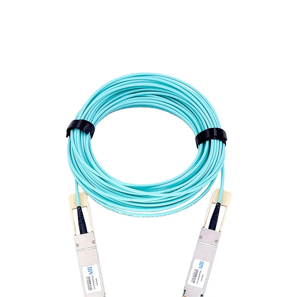
BiDi SFP+ changes the geometry: each module uses a single fiber pair directionally separated by wavelength, so you can run one strand where you previously needed two. One of the most common decisions network engineers face is selecting between single fiber SFP and dual fiber SFP modules. This comprehensive guide explores the differences between single and dual fiber SFPs, their respective benefits, limitations, and use cases—helping you make an informed choice. A single fiber SFP, also known as a BiDi SFP, is designed precisely for this purpose—enabling bidirectional data transmission over a single strand of optical fiber. Unlike traditional SFP transceivers that require two fibers—one for transmitting and one for receiving—a single fiber SFP uses. SFP (Small Form-factor Pluggable) is a compact, hot-pluggable network interface module used to connect network devices (switches, routers, firewalls) to fiber optic or copper cables. An SFP interface on networking hardware is a modular slot for a media-specific transceiver, such as for a fiber-optic cable or a copper. Both transmitting and receiving need one optical fiber to connect. Simplex SFP modules, also known as BIDI transceiver, employs a unidirectional transmission mechanism and have only one port. In practice, that means fewer splice points, smaller patch panels, and less conduit congestion—especially in retrofit buildings.
[PDF]

An optical module sends data as light through fiber cables. Light is faster than electricity, making it great for quick communication. The optical module serves as a crucial component in optical fiber communication systems, operating at the physical layer, which is the lowest layer in the OSI model. Its primary function is to achieve optoelectronic conversion by converting electrical signals into optical signals and vice versa. This technology is crucial for fast and reliable data transfer in networks. Optical modules typically have an electrical interface on the side that connects to the inside of the system and an optical interface on the side that connects to the outside. Optical fiber transmission forms the backbone of modern high-speed communication networks, enabling the efficient transfer of massive datasets across vast distances. These modules typically consist of a transmitter, which converts electrical signals into a light signal, and a receiver, which converts the received signal back. In high-speed data networks, the seamless integration of fiber optic cables with SFP (Small Form-Factor Pluggable) modules is critical for reliable signal transmission. SFP transceivers bridge electrical and optical signals, making them indispensable in data centers, telecom networks, and.
[PDF]

When it comes to testing fiber optic cables, a Visual Fault Locator (VFL) is an essential tool in your toolkit. A VFL is used to detect faults, breaks, or bends in fiber optic cables by emitting a bright red light that is visible even through the fiber's jacket. Let's dive into everything you need to know about mastering VFLs. In the. Finding a break in a fiber optic cable can be challenging but is essential for maintaining a stable network. Common Indicators of a Cable Break Signal. Here Kingfisher's experienced engineers share their experience in best practices and procedures for fiber optic testing related mostly to installation and maintenance. We hope that by sharing our knowledge, we will help grow our industry. Please enjoy & pass on these notes. The following are key methods and techniques used for optical fiber cable line failure positioning: Visual Inspection: Perform a visual inspection of the. Locating faults in fiber optic cables requires specialized tools and techniques. Look for dirt, scratches, or damage on the connectors. Clean. To ensure the quality and continuity of fiber optic services, it is essential to identify and locate fiber optic cable faults as quickly and accurately as possible. In this article, you will learn about some of the common methods and tools for fiber optic testing and troubleshooting.
[PDF]

If you're leading a project involving fiber—whether for a healthcare facility, retail expansion, or OEM partner network—this guide will walk you through every technical phase of planning a fiber optic installation from scratch. Before we dive in, understand this:. Building a fiber optic network is a highly technical yet vital process that enables communities and businesses to access high-speed, reliable fiber optic internet. From the initial site survey to the final fiber to the home (FTTH) connection, every stage requires careful planning, coordination, and. The Fiber Optic Association, Inc. (FOA) was founded in 1995 to help develop the workforce to build the fiber optic networks to support a rapid expansion in communications and the Internet. It includes first determining the type of communication system (s) which will be carried over the network, the geographic layout (premises, campus, outside. Optical Fiber Cable Engineering Construction: A Comprehensive Operation Guide 1. This recommended practices document is a comprehensive manual for optical fiber construction and testing. Sections are included for project management; cable handling, testing and equipment; overhead cable placement; underground cable placement; underground enclosures; bonding and grounding; cable.
[PDF]

IEC fiber connector standards establish the global specifications for connector geometry, mating interfaces, optical performance classes, and mechanical testing across all fiber network environments. Optical connectors are used to connect optical devices to other optical devices or systems. However, each connection introduces a certain amount of insertion and return loss that. Connectors play an important role in Enterprise network architecture. They give you the power to add, drop, move, and change the network. is a small cylinder used to mount. The Fischer FiberOptic Series offers robust and faultless optical performances in any conditions. Combined with easy use, cleaning and maintenance. Tested for harsh and extreme environments (Norm IEC 61753-1 Cat. These standards ensure that passive fiber-optic components remain interoperable, stable, and. designed for diverse fiber optic applications. But what exactly sets a fibe optic connector apart in terms of its merits? The primary purpose of a fiber optic connector is to terminate the ends of fiber optic cables, ensuring they can be int rconnected reliably with minimal optical loss. After. Fiber optic technology is used in ever-increasing applications due to its inherent advantages (lower weight, EMI/RFI immunity, higher bandwidths and distances) over copper. There are many.
[PDF]

Optical couplers can split or join signals in fibers. You can connect many users to one port with 1:n or 2:n splitters. These devices work both ways, which helps strong network communication. They help send. This small device connects or joins optical fibers together. It helps networks grow and change when needed. Learn about the two main types of fiber optic couplers: fused and planar. Fused. How to Choose the Right Fiber Coupler (FTTH, Data Center & More) Are you in the process of designing a Fiber to the Home (FTTH) network, but wondering how to split one fiber for multiple users? Or maybe you are operating a data center, and you would like to use a single signal to provide to. Fiber optic couplers are optical devices that connect three or more fiber ends, dividing one input between two or more outputs, or combining two or more inputs into one output. The device allows the transmission of light waves through multiple paths. Fiber optic couplers can either be passive or. A fiber optic coupler is a passive optical component that splits, combines, taps, or redistributes light between optical fibers. In real-world networks, couplers let one signal reach many users, allow several signals to share one fiber path, or sample a small amount of light for monitoring. 5/125 µm fiber, with low insertion loss and a broad operating wavelength range from 800 to 1600 nm. The 1x2 and 2x2.
[PDF]
