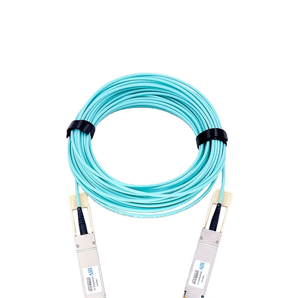
A bundle fiber optic cable refers to a type of optical fiber cable where multiple individual fibers are grouped or bundled together within the same outer sheath. Stranded fiber optic cable is a loose tube made of high-modulus plastic by adding colored optical fiber and ointment at the same time, and the optical fiber can move in the tube. Different loose tubes are twisted along the central reinforcing core to make the cable core. Instead of having individual round cables, ribbon cables have several fibers laid out side by side, typically in a flat and compact. 📦 For purchasing, use the RP Photonics Buyer's Guide for fiber bundles. It provides an expert-curated supplier directory, buyer-focused technical background information, and structured selection criteria to support professional procurement decisions. What is a Fiber Bundle? For some applications. Fiber optics, or optical fibers, are long, thin strands of carefully drawn glass about the diameter of a human hair. These strands are arranged in bundles called fiber optic cables. We rely on them to transmit light signals over long distances. This article is going to introduce fiber optic bundles, and it is configuration examples, benefits, and applications. Because the cross-section of a single optical fiber is too thin, it is not suitable for transmitting images or light, so this function is achieved by.
[PDF]
The G202-xxU-6LC is a six-core multi-mode finished fiber cable, which is mainly used with audio and video optical fiber extenders. This six-core multi-mode 50/125 OM3 fiber with LC-type connectors can transmit up to 300 meters while maintaining a 10Gbps bandwidth. Optical fibres contained in a jelly filled mono/loose tube, aramid yarn reinforced, PE sheathed with Nylon oversheath. Designed for duct installation or direct burial, where water or termite resistance are required. Note: Minimum order quantity applies to these options. The OS1 fibre is specified. If this product is Out of Stock. Please visit 4Cabling for a similar range of products. Imm (main cord) Material Stainless Steel Color Silvery White UL94 V-0 (*Burning stops within 10 seconds on a veritcal specimen, no drips of flaming particles. ) *Exact product code is subject to the cable length. Specifications are correct at time of printing and subject tochange or alteration. öGIG is a telecommunications company that specializes in designing and operating Fiber to the Home (FTTH) fiber optic networks in underserved communities in Austria, offering high-performance 100% fiber internet connections directly to households. This initiative supports the Austrian government's. Fiber Optic Cables Priced Per Foot, chainflex CFLG fiber optic cable TPE 62. Highly customizable designs with a wide range of coatings available.
[PDF]

Fibre-optic Link Around the Globe (FLAG) is a 28000km (17,000miles) fibre optic mostly- submarine communications cable that connects the United Kingdom, Japan, India, and many places in between. The cable is operated by Global Cloud Xchange, a subsidiary of RCOM. These cables stretch thousands of kilometres beneath the sea, carrying the digital world across continents. New Delhi: Internet is an inseparable part of life in this modern world. Social media. These undersea cables carry almost all international data, connecting continents and countries. They're like the invisible highways of our digital world. Today, tech giants like Google, Facebook, Amazon, and Microsoft own or lease more than half of the undersea bandwidth. The world depends on digital links and the control of these cables decides how information moves between. Private telecom and technology companies own and operate nearly all submarine internet cables, which carry 99% of global internet traffic. These companies invest heavily in laying and maintaining the vast network of fiber-optic cables that connect continents and enable international data flow. The system runs from the.
[PDF]

A distribution box, also known as a fiber distribution hub or optical distribution box, is a larger enclosure designed to manage and distribute fiber optic cables to multiple endpoints. It serves as a central point for connecting and organizing numerous fiber optic. Although all three are related to fiber connection and management, their installation locations, functional roles, and positions within the network architecture are fundamentally different. Confusing these devices may lead to non-standard cabling at best, and serious challenges in network. In modern FTTH (Fiber to the Home) and optical communication networks, three types of fiber distribution products are widely used: Splitter Distribution Box, ODF (Optical Distribution Frame), and Fiber Terminal Box. The functions of the four connectors can be. First, let us learn the common point among ODF, fibre optic termination box and fiber optical distribution box, actually, they have similar function, we sort out them as following 4 aspects: 1. fiber termination and optical signal splitting 4. What is the difference between these fiber boxes.
[PDF]

Plan your outdoor fiber installation carefully by surveying the site, choosing the right cable type, and following FOA and OSP standards to ensure reliability. Select the best installation method—direct burial, aerial, conduit, or underwater—based on your environment and. Outdoor fiber optic cables are critical for building stable, high-speed networks in real-world environments. Whether you're linking buildings, running broadband in rural areas, or building 5G infrastructure, the right cable matters. It affects performance, maintenance, cost, and reliability. Use. Choosing an outdoor-rated fiber optic cable requires balancing protection, durability, and performance. This guide highlights five top options designed for challenging installations—from roads and construction sites to outdoor telecom runs. Each option includes armor, low-friction jackets, and UV. Fiber optic cables enable high-speed, long-distance data transfer, forming the backbone of modern communication. Yet, outdoors, they face temperature swings, moisture, UV exposure, rodents, and human interference. However, choosing the proper cable can be daunting. Unlike internal cables, where several factors are neglected, external cables are designed with the understanding that they will be subjected to environmental extremes.
[PDF]

An Optical Distribution Frame (ODF) is a dedicated unit designed to organize, terminate, and interconnect fiber optic cables. It brings together fiber splicing, patching, and cable routing in a single structure, while shielding sensitive connectors and splices from mechanical. Effective fiber optic cable management helps you ensure stable networking and high-speed data transfer. As you work in the telecommunications field, you face complex challenges from rapid network growth and increasing data demands. Traditional methods can slow down your operations and increase the. In the complex architecture of fiber optic networks, the Optical Distribution Frame (ODF) serves as the linchpin for organizing, protecting, and distributing optical signals. Whether in data centers, telecom central offices, or enterprise network rooms, ODFs enable efficient fiber management. The growing reliance on fiber puts greater importance on how networks are physically built and maintained. Cable management is the practical side of that: planning how fibr is routed, secured, and accessed to keep the network performing as it should and ready to expand when needed. Good fiber optic. Proper cable management not only ensures stability but also extends the lifespan of fiber links and improves serviceability. In this article, we will discuss what makes ODF essential for cable management. What is ODF? ODF, also.
[PDF]

Scattering accounts for the greatest amount of attenuation in a fiber cable, between 95 and 97 percent. Light traveling through the fiber interacts with the densities as shown in the light and is then partially scattered in all directions. Fiber optic cables have many advantages, but one of the downsides just like with copper cable, is that it can experience what is called attenuation. Attenuation refers to the loss of light as it travels down the fiber. This can be due to a variety of factors: scattering and absorption, intrinsic. This attenuation is inevitable, so the smaller the attenuation value, the longer the transmission distance of the same optical power. The better the quality of this fiber patch cable. It indicates the amount of signal reflected back. At TREND Networks, we are frequently asked how much loss is allowed when conducting testing on fiber optic cabling. Unfortunately, it is not a simple answer and depends on several factors. So how do you determine acceptable loss? When testing fiber optic cabling, determining acceptable loss is. Understanding fiber loss is vital in maintaining a reliable, efficient network. Understanding it is crucial for anyone involved in data centers, telecommunications, or enterprise networking. Here are the details and instructions about each field and how they contribute to the calculation: 1. Attenuation Coefficient (dB/km): This value represents the inherent signal loss per kilometer of.
[PDF]

When Batelco was first founded in 1981, Bahrain already had 45,627 telephone lines in use. By 1982, the number reached 50,000. Batelco enjoyed being a monopoly in the telecommunications sector for the next two. Telecommunications in Bahrain are provided by the Bahrain Telecommunications Company, trading as Batelco, as well as other companies such as Zain and STC. Prior to 1981 telecommunications services were provided by two separate departments: national services were provided by the Bahrain. Explore the evolution of BNET in Bahrain, a testament to the nation's commitment to advancing telecommunications infrastructure and connectivity. BNET won the Gigacity Excellence Award at the WBBA Broadband Excellence Awards 2024! Learn about BNET's evolution and its journey to provide advanced. alth, and to maintaining national competitive advantage. Change in information and telecommunications technology (ICT) has accelerated over the last two ecades, and these two areas have increasingly converged. Since then, other companies such as Zain and VIVA have entered the telecommunications sector. During the same year, Optical fibres and cables were the 479th most exported product (out of 3,333) in Bahrain. In 2024, the main destinations of.
[PDF]

l LongXing GPJ83-D18 fiber optic splice closures are specially designed to protect joints of optic cable. l The scope of application is: aerial, wall-mounting, and pole-mounting. The ambient temperature ranges from –40℃ to +65℃. l The closure adopts mechanical and heat shrinkable. The GPJ83-D18 Dome Fiber Optic Splice Closure are closures which accommodate the joint part of the cable, that can be used in aerial-hanger, wall-mounting or pole-mounting. This kind of dome splice closure includes three types, namely GPJ83-D18-A, GPJ83-D18-B, GPJ83-D18-C, GPJ83-D18-D, which. –High strength dust proof and waterproof function, suitable for aerial installation –The box body adopt push pull mechanical locking mode, with design of buckle type, easy to operate, reusable and reliable –Adapter and splitter can be assembled, 18pcs adapter can be equipped UV, 2pcs micro. Up-down bisection GPJ-M is an arc, horizontal type. Innovative insert plates and fixing bolts are used to fix and seal FOSC, and its installation is quite simple. The FOSC is suitable for protecting fiber cable splices in straight-through and branching applications. Speed Optic' s closures can be divided into two series: horizontal type and dome type. As for dome type, according to the sealing ways, including shrinkable. Dome GPJ-O is a vertical type. GPJ-O is provided with 4 fiber cable inlet/outlet ports and sealing is achieved by tightening nut after inserting fiber cable.
[PDF]
G657A2 bending insensitive singlemode fiber combines two attractive features: excellent low macro-bending sensitivity and low water-peak level. It is comprehensively optimized for use in O-E-S-C-L band (1260 -1625 nm). FOSC ® 450 B6 Fiber Optic Splice Closure, Gel Cable sealing, no pre-installed tray, 6 cable attach., three ground feedthrough lugs, with test valve, Build America Buy America (BABA) Finish making your selections or clear them to view relevant specifications. B2 Including the IEC 60793-2-50 type Bl. b2 Optical Fiber Specification. Use the code in the “Fiber Type” column to replace the XX notation in the catalog number shown on the catalog page. This identifies the fiber that will be provided with the cable choice. The fibers in all completed cables are tested 100% at the factory for attenuation, and each fiber must meet the. trip force (Force to mechanically strip the and ≤ 5. low water-peak level. It is comprehensively optimized for use in O-E-S-C-L band. Outdoor dry core optical fiber Multi Loose Tube cable with glass yarns as strength member, Corrugated Steel Tape (Full Rodent Protected) armor and polyethylene outer jacket. Product feature: This cable has improved rodent protection by Corrugated Steel Tape (Full Rodent Protected). Existing out of.
[PDF]

Strip the cable the required length, minimum 0. 5 meter or more, to establish easy and safe installation with enough buffer size. Pass the stripped cable into the upper side of the splice tray. Fix the cable strength member (3) on part (2) and stabilize with cable fixing part. To establish easy and safe installation put the box where it will be installed and measure the required length of the cable. 5 meter or more, to. Lockable Cable inputs: 2x 12mm - 16x Space for 1x16 SC splitter or 1x32 LC splitter 1. Cable fixing Instert the stripped cable through the cable entry port and fasten the FRP element(s) to the block. The outher coating should be fasten useing the steel hops. Do not fasten too. Stripping and preparing fibre optic cables for termination is a critical step in the installation and maintenance of fibre optic networks. Firstly, it is important to consider that when stripping multi-layer cables for connectorization, each layer must usually be stripped individually, as they all usually need to be stripped to different lengths. Cutting and stripping the cable jacket can be done with a special fiber stripper or a properly set wire stripper as long as it does. Whether it is indoor or outdoor fiber-optic (FO) cable, using a step-by-step approach reduces the chance of fiber damage while ensuring the performance of fibers. In our continuing discussion of installing FO cables, let's use a step-by-step approach in detailing how to strip and clean indoor and.
[PDF]

When it comes to testing fiber optic cables, a Visual Fault Locator (VFL) is an essential tool in your toolkit. A VFL is used to detect faults, breaks, or bends in fiber optic cables by emitting a bright red light that is visible even through the fiber's jacket. Let's dive into everything you need to know about mastering VFLs. In the. Finding a break in a fiber optic cable can be challenging but is essential for maintaining a stable network. Common Indicators of a Cable Break Signal. Here Kingfisher's experienced engineers share their experience in best practices and procedures for fiber optic testing related mostly to installation and maintenance. We hope that by sharing our knowledge, we will help grow our industry. Please enjoy & pass on these notes. The following are key methods and techniques used for optical fiber cable line failure positioning: Visual Inspection: Perform a visual inspection of the. Locating faults in fiber optic cables requires specialized tools and techniques. Look for dirt, scratches, or damage on the connectors. Clean. To ensure the quality and continuity of fiber optic services, it is essential to identify and locate fiber optic cable faults as quickly and accurately as possible. In this article, you will learn about some of the common methods and tools for fiber optic testing and troubleshooting.
[PDF]

The optical power meter is similar to the voltohmmeter in application but measures the optical resistance (losses measured in dBm or dBM) of a cable before and after installation and provides a comparative analysis of the splices. The range of the meter is adjustable. Regularly testing fiber optic cables helps minimize network downtime, lengthens the network's longevity, reduces maintenance requirements, and helps support network reconfiguration and upgrades. These factors significantly add to the fiber optic network's long-term performance, manageability, and. Several types of tests are commonly conducted to assess and maintain the health of fiber optic networks. Continuity testing verifies that the fiber is intact and that light can pass through from one end to the other without any blockages. These test procedures assess the physical and functional qualities of fiber optic cables, connectors, and the network as a whole. Key tests include: Effective fiber testing utilizes advanced tools such as Optical. One way to test a splice is to use an Optical Power Meter. As the components like fiber, connectors, splices, LED or laser sources, detectors and receivers are being developed, testing confirms their performance specifications and helps. Regular testing of fiber optic cables is not just a preventive measure; it's an investment in the longevity and efficiency of your network. By identifying potential issues early, you can enhance.
[PDF]