
Mechanical Optical Switches: Switching times typically range from 1-10ms, suitable for long-distance transmission scenarios where latency is not critical (such as backbone network protection switching). Solid-State Optical Switches: Based on thermooptic or electrooptic effects, response. We lead the industry in optical switch technology, delivering the lowest insertion loss (0. 2 dB), fastest switching speed (10 ns), broadest wavelength range (300–2400 nm), widest fiber compatibility, highest optical power handling (50 W), and space-qualified reliability. Backed by over 25 years of. Use this optical switches buying guide to compare major types, define selection criteria, and find suppliers: Professional purchasing of high-value photonics products is a substantial responsibility, where a structured decision-making process is essential. RP Photonics offers a lot of help: Get. This document is a troubleshooting and selection guide for common optical switch failures, compiled based on over 500 field cases. These switches are built on proven, reliable optomechanical technology that has seen more than 30 years of successful operation. Each. The POLATIS ® Series 7000 384x384 all-optical circuit switch is designed to meet the most demanding applications with exceptionally low optical loss, compact size, and fast switching speeds. With support for Software-Defined Networks (SDNs) via embedded NETCONF and RESTCONF control interfaces, the.
[PDF]

Splice Diagrams or Matrices capture an electric or optical network inside a location – documenting cables, ported equipment, and connections. Splices are fiber-to-fiber, port-to-fiber and port-to-port. Fiber optic cable splicing involves joining two fiber optic cables together. Another method of connecting optical fibers is termination or connectorization, which consists of processing the end of a fiber optic bundle so that it can be connected to other fibers or devices through fiber optic. In this guide, we cover the basics of fiber optic splicing, how to perform splicing using two different methods, and finally some best practices to perform good fiber splicing. Ensure Your Splicing Tools are Clean – #2. Use and Maintain Your. What to show on a network diagram? Fiber optic network diagrams represent the architecture and connectivity of fiber optic systems, and their design philosophy integrates technical, functional, and conceptual aspects. The diagrams abstract complex details of fiber optic systems to make them. This Geoschematics drawing remains easy to read despite containing more than 2000 fibers and 500 splices. All students and instructors must wear safety glasses in this lab. It is copyrighted by the FOA and may not be distributed without FOA permission. This VHO covers similar material to the videos on YouTube. The lab manual has several.
[PDF]

An SFP port on a gigabit switch works by allowing interchangeable transceiver modules to slot in. These modules convert electrical signals into optical or copper signals, depending on the type you use. You can choose between short-range or long-range, fiber or copper . At Network-Switch. com, we specialize in Cisco-compatible and NS Comm transceivers, offering enterprise customers tested, certified, and globally supported optical solutions. Cisco offers a range of GBIC transceivers and Small Form-factor Pluggables (SFP) transceivers for Gigabit Ethernet and Fibre Channel appications. These small, modular optical interface transceivers offer a convenient and cost effective solution for the adoption of Gigabit Ethernet and Fibre Channel. The SFP port, or Small Form Factor Pluggable in industrial switch is designed for use with SFF (Small Form Factor) connectors and provides high speed and small physical size. With this, it allows to extend the functionality of the device with additional communication standards. The hot-swappable input/output device plugs into a Gigabit Ethernet port or slot. Optical and copper models can be used on a wide variety of Cisco.
[PDF]

In this article, we break down the major FTTx models, compare their performance and implementation contexts, and showcase how LINK-PP's high-performance optical modules support each deployment type. Huawei's fiber to the room (FTTR) solution extends fibers to rooms and provides various gigabit Wi-Fi 6 master/slave FTTR units, all-optical components, and optical cable construction tools, enabling users to enjoy stable gigabit Wi-Fi experience in every corner of rooms at every moment. In. Fibre-to-the-room (FTTR) delivers Gigabit optical capacity directly to each room in a building, providing very high-speed, reliable internet. FTTR fibre-based technology: designed to enhance digital capabilities. FTTR addresses challenges related to restricted speeds within buildings, providing. Fiber to the Room (FTTR) is a next-generation access network designed to deliver high bandwidth, low latency, and room-level optical coverage. It is envisaged that the topology and functionalities of FTTR technologies may be. Fiber to the Room (FTTR) is a possible solution to issues with indoor connectivity. Demands for high bandwidth, high bit rates in both directions, low latency, and service reliability are constantly growing. FTTR is a very effective way to improve the quality of residential broadband service and reduce customer complaints, more so with the advent of Wi-Fi 7.
[PDF]
Fiber-Mart offers most affordable high performance MEMS optical switches. The MEMS technology offers extremely low electrical power consumption, high durability (> 1x10^9 cycles), no stiction, and high resistance to shock & vibration. Sercalo's optical MEMS switches are the best choice for optical switches in Network supervision and optical test and measurement because they exhibit solid state reliability, ultra small insertion loss and long-term stability. Since 1999 Sercalo Microtechnology Ltd. supplies optical MEMS solutions. These MEMS single mode switches are designed to be easily integrated into optical systems. The switch is packaged to. MEMS-based switches offer high reliability that passed well over 10⁹ cycles of switching tests. The 1D motion MEMS mirror (in or out of the light path) offers low crosstalk or high on/off ratio, fault-safe latching, free space platform. The 2D. Or specify any custom connector requirement Download the Optosun Optical switch Mems PDF - Opens in new window. Orbray's MEMS (Micro Electro Mechanical System) Optical Switch are designed a small footprint package with providing low insertion loss, flat wavelength dependence loss (WDL), low polarization dependence loss (PDL) and performing less than 1ms/10ms switching speed. Well designed by the professional engineers, MEISU's capacitive MEMS switches are all featured with compact size, high channel count and long life time.
[PDF]

Insertion loss tells you how much weaker the signal becomes after passing through the splitter. Let's say you have a laser output at 0 dBm (which is 1 milliwatt of optical power). If you use a 1×8 splitter with ~10. 5 dB of insertion loss, the power at each output would be: 0 dBm – 10. 5. Enter excess loss from the splitter datasheet for your wavelength. Add connector and splice quantities with realistic planning losses. Include any additional component losses and an engineering margin. Enable power budget to estimate received power and margin. Press Calculate to show results above. Understanding optical splitter loss isn't just about plugging numbers into a calculator. It's about knowing what factors contribute to that loss, how manufacturers specify it, and how it impacts the overall performance and reach of your network. Ignore it, and you might find your signal too weak to. Optical insertion loss refers to the signal loss resulting from the insertion of components such as connectors or splices in an optical fiber system. Common ratios: For cascades, add losses and validate margin using the Optical Budget tool. This Fiber Optic Splitter Insertion Loss is the splitter devices loss, Considering fiber connectors or connectors+adapter insertion loss in LGX, The fiber splitter IL would be a little bigger. To make clear the basic ftth fiber splitter loss in performance, You can refer to the below loss chart.
[PDF]

Remove and reinstall the optical module. If the fault persists, replace the optical module with a normal one of the same type to check whether the optical module is faulty. The optical module is faulty or not securely installed. The device management or driver software has a bug. If the optical module is installed on a GE port, run the display interfaceGigabitEthernet x/x/x command to view port information when the optical module is inserted, including the rate and wavelength. Have you ever dealt with sudden network drops from faulty optical modules? Issues like this cannot only break communications, but they can really jeopardize business continuity. Understanding how to troubleshoot and prevent a failing optical module is vital for good network stability. This article. Huawei switches using non-certified optical module may not be able to read the information, can not guarantee the accuracy of the information read, recommend the use of Huawei certified optical switch module. Page 5 Changes in Issue 01 (2017-09-10) This issue is the first official release. The software version of this issue is V800R010C00. Issue () Huawei Proprietary and Confidential Copyright © Huawei Technologies Co. Page 8 40º C if a 40º C if a at 40º C if a single fan single fan single fan. The device cannot display any optical module information but services are running normally.
[PDF]

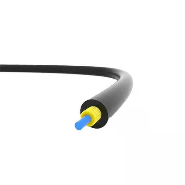
The diameter of a circle is the total width across the center and the radius is the distance from the center to the circumference. The normal recommendation for fiber optic cable is the minimum bend radius under tension during pulling is 20 times the diameter of the cable (d). When not under. Bend radius is the amount of bending that can occur before a cable may sustain damage or increased attenuation and limit bandwidth performance. Bending can also permanently. The Cable Outer Diameter (OD) refers to the total cross-sectional width of a fully assembled cable, measured from the outermost edges of its exterior jacket. In network engineering and telecommunications, evaluating the cable OD is critical for calculating conduit fill capacity, determining the. Bend radius, which measures the inside curvature of the cable, is the minimum radius installers can bend optical fibers without damaging their performance. It is a vital parameter that enables installers to guarantee that fiber optic cables are efficient and durable. Fiber optic cable bend radius is a critical mechanical parameter that determines how sharply a cable can be bent without risking microbending, macrobending, signal loss, or long-term structural fatigue. Proper bend radius control ensures the integrity of optical performance and protects the glass.
[PDF]

RFP Publishing Period: from November 12th, 2025 to 14h00, November 26th, 2025 (GMT+6:30), during MYTEL's office hours — from 8h00 to 17h30, Monday to Friday. 61-63, Zoological Garden Rd., Dagon Township, Yangon, Myanmar. We have identified 63 global optical fibre cable tenders from the public procurement domain worldwide. View the latest global tenders for optical fibre cable from Africa, the Americas, Asia, Australia, Europe, the Middle East, and other countries. Find global tender information, RFPs, RFQs, ICBs. Mytel Announcement on Invitation to Bidding No. RFP 134/2025/MYTEL-OPTICALCABLE – “Purchase OPTICAL CABLE for Mytel”. Requesting Party: TELECOM INTERNATIONAL MYANMAR CO., LTD. Tender For Provision of Fiber-optic internet services for OCHA in Sudan., communication channel rental services (fiber-optic communication channel rental services in the city of makinsk. Please click here to see the Current Opportunities. Procurement of Furniture and Equipment for the support to operationalize Public Procurement Act. Are you searching for the latest Fiber Optic Cable Tenders from trusted sources across the globe? Tender Impulse is the go-to tender website for businesses seeking verified and timely updates on public tenders, government tenders, and business tenders in a wide range of sectors.
[PDF]

The receiver of an optical module has an overload point. Therefore, an optical attenuator is required to reduce the optical power. By introducing a precise and constant amount of optical loss, it ensures that the incoming signal remains within the optimal operating range of the receiver. A. Average optical power refers to the optical power outputted by the optical module's transmitter under normal working conditions, which can be understood as the intensity of light. The transmitted optical power is related to the proportion of "1"s in the transmitted data signal; the more "1"s, the. The receiver of an optical module has an overload point. If the optical power received by the receiver is excessively high, the optical module will be burnt. In addition, during signal transmission in a WDM system, the. 📦 For purchasing, use the RP Photonics Buyer's Guide for optical attenuators. It provides an expert-curated supplier directory, buyer-focused technical background information, and structured selection criteria to support professional procurement decisions. Optical attenuators are devices that. An optical attenuator, or fiber optic attenuator, is a device used to reduce the power level of an optical signal, either in free space or in an optical fiber. Optical internetworks are data networks composed of routers and data.
[PDF]

An ideal optical splitter will distribute the light power according to mathematical principle. This is because each of the 8 output ports of the splitter will receive only one-eighth of the. Thorlabs' Single Mode 1x8 Fiber Optic Planar Lightwave Circuit (PLC) Splitters allow a user to split a single input signal evenly into eight output signals, which is ideal for passive optical networks (PON) and other high-channel-count applications. 1×8 splitter means it takes one input fiber and splits the signal into eight outputs. It doesn't need power — it's passive! Great for sharing one signal with many devices, like in FTTH (Fiber To The Home) networks. But light doesn't just split for free. Sharing means each output gets less than the. If we operate with absolute gains measured in relation to 1 milliwatt (mW), they are expressed in dBm, and are calculated as follows: Power Level (dBm) = 10 lg ( mW / 1 ) For “household” needs, in order not to calculate mW to dBm and vice versa every time, here's a ready-made correspondence table:. For instance, a 1:8 splitter ratio signifies an equal distribution of incoming optical power among eight output ports, with each port receiving 1/8th of the total power. It has one input port and eight output ports, making it ideal for applications where a signal needs to be.
[PDF]
As an essential component of optical fiber communication, optical modules are optoelectronic devices that facilitate the conversion between optical and electrical signals during the transmission process. Operating at the physical layer of the OSI model, optical modules are core devices in optical. The optical module serves as a crucial component in optical fiber communication systems, operating at the physical layer, which is the lowest layer in the OSI model. Classification of Optical Module: Distinguished according to function, package form, transmission rate, wavelength. In the era of 5G, AI, and high-speed data centers, optical modules serve as the core bridge for converting electrical signals to optical signals (and vice versa), enabling fast, reliable data transmission across networks. They are used in fiber optic communication systems to transmit data over long distances with minimal loss and interference. These modules typically consist of a laser or LED transmitter, a.
[PDF]

These easy-to-install 20" cable channels can be painted, cut and even turn a 90º angle. Simply attach the uniquely designed wall clips to the wall, secure cables and wires to the fasteners and snap the tunnels onto the clips. Kit includes three long cable . Corning has a wide variety of hardware solutions to choose from to fit your cabling needs. Choose from racks, panels, modules, splice trays, ethernet fiber switches and other structured cabling components. Corning has a variety of hardware solutions including ethernet fiber switches, panels, racks. Often over looked, utilizing tunnel systems to deploy fiber optics, can provide last-mile and intra-city broadband pathways by providing immediate, cost-e ective, and durable deployment routes without disrupting the municipality or mother nature. This fact presents Transit Operators with a unique. Cable Tunnel Kit: The Sanus ELM301 is a cable tunnel kit that conceals and routes even the most complex cable arrangements. This concept significantly optimises the lighting installation. Precision Group's Optical Network Terminals are engineered to safeguard both the ONT and fiber, serving as a secure, all-in-one transition point. Based on customer feedback, our latest optical network terminal designs now include Keystone Ports for router and phone connections, enhancing.
[PDF]
