An optical time-domain reflectometer (OTDR) is an instrument used to characterize an. It is the optical equivalent of an electronic which measures the of the or under test. An OTDR injects a series of optical pulses into the fiber under test and extracts, from the same end of the fiber, that is scattered () or reflected ba.
[PDF]
Time domain reflectometers are commonly used for in-place testing of very long cable runs, where it is impractical to dig up or remove what may be a kilometers-long cable. They are indispensable for preventive maintenance of telecommunication lines, as TDRs can detect resistance on joints and connectors as they corrode, and increasing insulation leakage as it degrades and absorbs. OverviewA time-domain reflectometer (TDR) is an electronic instrument used to determine the characteristics of by observing. It can be used to characterize and locate faults in metallic cables (for. A TDR measures reflections along a conductor. In order to measure those reflections, the TDR will transmit an incident signal onto the conductor and listen for its. If the conductor is of a uniform.
[PDF]

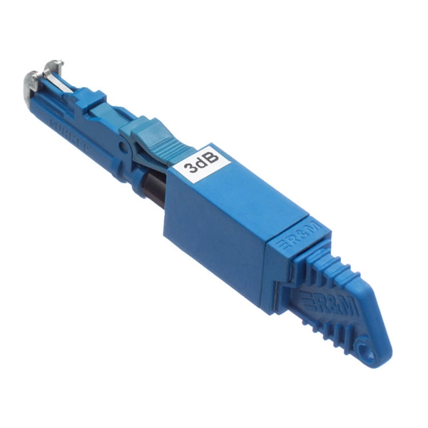
Optical attenuators use several principles in order to accomplish the desired power reduction. The types of attenuators generally used are fixed, stepwise variable, and. An optical attenuator is a passive device that is used to reduce the power level of an optical signal. The attenuator circuit will allow a known source of power to be reduced by a predetermined factor, which is usually expressed as decibels. Key requirements include minimal effect on the beam profile, low wavelength and polarization dependence, and sufficient power handling capability. The basic types of optical attenuators are fixed, step-wise variable, and continuously variable. Since too much light may saturate the fiber optic receiver, optical attenuators are often deployed in the system to reduce the light power and achieve the best fiber. An attenuator is a device designed to reduce the intensity of electrical and electromagnetic oscillations smoothly, stepwise, or at a fixed rate. It primarily ensures the power or amplitude of a signal is lowered without significantly distorting its waveform. Attenuators are extensively used across.
[PDF]

On average, you can rent a Fusion Splicer for $275/day, $773/week, $1424/month. The price of these splicers can be higher because of their mechanical complexity and ability to handle various fiber types, including large-core fibers. Hybrid splicers bring in various features that are present in both automatic splicers and manual splicers. They can be aligned by the core. Fiber optic fusion splicers are critical tools for deploying and maintaining fiber networks, with significant variations in performance, features, and pricing. This guide breaks down the key cost-influencing factors across five dimensions—splicer types, technology, performance, accessories, and. A fiber optic splicing machine is a specialized machine used to fuse two optical fibers together to form one long one. The machine, also known as a fiber optic fusion splicer, uses electricity to melt the two optic cables into one. The fiber fusion splicer conducts the fusion with high accuracy to. Check each product page for other buying options. Get reliable equipment with fast splicing times and comprehensive accessories included. It features a mini handheld design, integrated buttons and touch screen, simple operation, low.
[PDF]

Remove and reinstall the optical module. If the fault persists, replace the optical module with a normal one of the same type to check whether the optical module is faulty. The optical module is faulty or not securely installed. The device management or driver software has a bug. If the optical module is installed on a GE port, run the display interfaceGigabitEthernet x/x/x command to view port information when the optical module is inserted, including the rate and wavelength. Have you ever dealt with sudden network drops from faulty optical modules? Issues like this cannot only break communications, but they can really jeopardize business continuity. Understanding how to troubleshoot and prevent a failing optical module is vital for good network stability. This article. Huawei switches using non-certified optical module may not be able to read the information, can not guarantee the accuracy of the information read, recommend the use of Huawei certified optical switch module. Page 5 Changes in Issue 01 (2017-09-10) This issue is the first official release. The software version of this issue is V800R010C00. Issue () Huawei Proprietary and Confidential Copyright © Huawei Technologies Co. Page 8 40º C if a 40º C if a at 40º C if a single fan single fan single fan. The device cannot display any optical module information but services are running normally.
[PDF]

This report provides an in-depth analysis of the global Optical Module Package market, offering critical insights for stakeholders navigating this dynamic sector. The global Optical Modules market is projected to grow from US$ 17590 million in 2024 to US$ 56786 million by 2031, at a CAGR of 15. 8% (2025-2031), driven by critical product segments and diverse end‑use applications, while evolving U. tariff policies introduce trade‑cost volatility and. The Optical Module for AI Market Size was valued at 5. 08 USD Billion in 2024. 7% during the forecast period MARKET INSIGHTS The global Optical Module Package Market was valued at 8942 million in 2024 and is projected to reach US$ 20220 million. Optical Module Package by Application (Telecommunications, Data Communication), by Types (SFP/eSFP, XFP /SFP+, QSFP+/QSFP28, CXP/CXP2, CFP/CFP2, QSFP-DD), by North America (United States, Canada, Mexico), by South America (Brazil, Argentina, Rest of South America), by Europe (United Kingdom. Optical Modules Market Revenue was valued at USD 3. 2 billion by 2033, growing at a CAGR of 10. 3% from 2026 to 2033. This growth is primarily driven by the increasing demand for high-speed internet and data transfer capabilities across various.
[PDF]

Urban Areas: 25–40m spacing (concrete poles, 10–12m height)., steel lattice structures). Factors: Cable weight (kg/km) Ice loading (up to 50mm. The Fiber Optic Association, Inc. (FOA) was founded in 1995 to help develop the workforce to build the fiber optic networks to support a rapid expansion in communications and the Internet. The charter of the FOA was to promote professionalism in fiber optics through education, certification, and. to n utral comm. cable R. FO-CS JOINT USE CLIMBING SPACE REQUIREMENTS 51. APPENDIX A - COVER SHEET / TOC 52. RUS DRAWING #PM12 58. CHECK. d suppliers of electrical construction services. They define a minimum baseline of quality and workmanshi for installing electrical products and systems. NEIS® are intended to be referenced in contrac documents for electrical construction ation or liability to users of this publication. Choose the type of pole The basic pole height is 7m and the tip diameter is 150mm. In case of special sections, crossing obstacles or roads or railways, the pole height of 8m, 9m, etc. can be selected. Cables 300 V or less need to be a minimum two feet over the street light. Climbing Space is an unobstructed, vertical space along the side or corner of the pole. In gen-eral, it consists of an imaginary box, 30-inches square, extending at least 40 inches above the highest communications cable or.
[PDF]

An ideal optical splitter will distribute the light power according to mathematical principle. This is because each of the 8 output ports of the splitter will receive only one-eighth of the. Thorlabs' Single Mode 1x8 Fiber Optic Planar Lightwave Circuit (PLC) Splitters allow a user to split a single input signal evenly into eight output signals, which is ideal for passive optical networks (PON) and other high-channel-count applications. 1×8 splitter means it takes one input fiber and splits the signal into eight outputs. It doesn't need power — it's passive! Great for sharing one signal with many devices, like in FTTH (Fiber To The Home) networks. But light doesn't just split for free. Sharing means each output gets less than the. If we operate with absolute gains measured in relation to 1 milliwatt (mW), they are expressed in dBm, and are calculated as follows: Power Level (dBm) = 10 lg ( mW / 1 ) For “household” needs, in order not to calculate mW to dBm and vice versa every time, here's a ready-made correspondence table:. For instance, a 1:8 splitter ratio signifies an equal distribution of incoming optical power among eight output ports, with each port receiving 1/8th of the total power. It has one input port and eight output ports, making it ideal for applications where a signal needs to be.
[PDF]

Find low everyday prices and buy online for delivery or in-store pick-up. Find low everyday prices and buy online for delivery or in-store pick-up. Shop products from small business brands sold in Amazon's store. Discover more about the small businesses partnering with Amazon and Amazon's commitment to empowering them. Learn more Made with chemicals safer for human health and the environment. Manufactured on farms or in facilities that protect. 20pcs Transmission Type Photoelectric Switch Optical Interrupter Sensor Opto. OPB825 Opto optical switch, photointerrupter. SA-6C Digital Toslink Optical 4x1 Switch with 3ft Optical Cable and IR Remote Contr. Get the best deals on optical switch when you shop the largest online selection at. Shop for Optical switcher at Best Buy. Networx® Gigabit Ethernet Fiber Media Converter - UTP to 1000Base-SX - ST Multimode, 5. Get fast shipping and top-rated customer service. Price when purchased online Cisco IE-4010-16S12P Ethernet Switch - 12 Ports - Manageable - Gigabit Ethernet - 1000Base-X, 10/100/1000Base-T - 3 Layer Supported - Modular - 16 SFP Slots - Optical Fiber, Twisted Pair - 1U - Rac. Live better. The FOSW-1x1 or 1x2 optical switch is based on opto-mechanical technology with proven reliability.
[PDF]

The answer is yes, and it's a practice widely used in the industry to distribute signals to multiple destinations without degrading the signal quality significantly. This article delves into the methods, benefits, challenges, and practical applications of splitting fiber lines. In principle, an optical cable can be split, but it's not as simple as just cutting the cable and attaching multiple devices. There are two primary methods of splitting an optical cable: Passive splitting involves using a specialized device called an optical splitter. This device takes the incoming. A fiber optic splitter is a passive optical component that divides a single incoming optical signal into two or more outgoing signals, or combines multiple incoming signals into one. What is Fiber Line. An optical splitter, also known as a beam splitter, fiber splitter, or fiber optic splitter, serves as a vital passive component in optical communication systems. Its primary function is to split the optical signal of one input optical fiber into multiple optical signals and transmit them to. An MPO breakout cable is a fiber optic cable designed to split a single multi-fiber connection into multiple separate connections. Fiber optic splitters have applications such as Fiber to the Home (FTTH) and Passive.
[PDF]
Optical cable junction boxes play a crucial role in connecting and protecting optical fibers, directly influencing the quality and lifespan of optical cable routes. Optical cable splice boxes protect the splicing parts of optical fibers from various hazards, such as water seepage due to adverse. Optical cable junction boxes play a crucial role in managing and organizing fiber optic networks. It serves as a termination point for fiber optic cables, providing protection and distribution of the optical fibers while ensuring efficient signal transmission. Utilizing an optical junction box can significantly enhance your. Optical cable splice box is a popular name, its scientific name is optical cable splicing box, also known as optical cable splicing package, optical cable splicing package and gun barrel. These boxes are designed to house and protect fiber optic splices and terminations, ensuring that the delicate fibers are safeguarded from.
[PDF]
The Open Systems Interconnection (OSI) model is a developed by the (ISO) that "provides a common basis for the coordination of standards development for the purpose of systems interconnection." In the OSI reference model, the components of a communication system are disting.
[PDF]