
By dividing a single optical signal from a central Optical Line Terminal (OLT) into multiple outputs for Optical Network Terminals (ONTs) at users' homes, splitters eliminate the need for dedicated fibers to each residence—slashing infrastructure costs while scaling network reach. High-speed broadband, cloud computing, and 5G communication all rely on one critical passive component: the PLC splitter. As a core device in FTTH and PON networks, a PLC splitter is not just about “splitting light” — it's about delivering stable, low-loss, and uniform optical power distribution at. In the backbone of modern Fiber-to-the-Home (FTTH) networks, optical splitters serve as the unsung heroes that enable cost-efficient connectivity for millions of subscribers. FTTH relies on Passive Optical Network architecture, which enables one fiber leaving the central office. 📄 What is an Optical Splitter? An Optical Splitter, also known as a beam splitter, is a passive optical device that divides a single input optical signal into two or more output signals. Conversely, it can also combine multiple signals into one. Think of it as a prism for modern-day fiber optic communications – directing the light in multiple directions, but without.
[PDF]

This report empowers stakeholders to capitalize on emerging opportunities, optimize product strategies, and outperform competitors through data-driven insights on sales, revenue, and forecasts across regions, by Type, and by Application for 2020-2031. Market Segmentation. The Optical Communication Tester Market was valued at USD 1. 2 billion in 2024 and is projected to reach USD 2. 5 billion by 2034, registering a CAGR of 7. This growth trajectory is underpinned by the increasing demand for high-speed internet and the proliferation of data centers, which require. According to our (Global Info Research) latest study, the global Optical Communication Tester market size was valued at US$ 722 million in 2024 and is forecast to a readjusted size of USD 1085 million by 2031 with a CAGR of 6. 0% during review period. An optical communication tester is a specialized instrument used to evaluate and troubleshoot. This report provides an in-depth analysis of the Optical Communication Tester market and highlights important drivers, challenges, and opportunities. By accessing this extensive data the major market players can make structured decisions to mitigate the complexities of this sector. The Optical. Optical Test Systems are specialized equipment designed to evaluate the performance, quality, and reliability of optical components and networks. The market is experiencing significant momentum due to the.
[PDF]

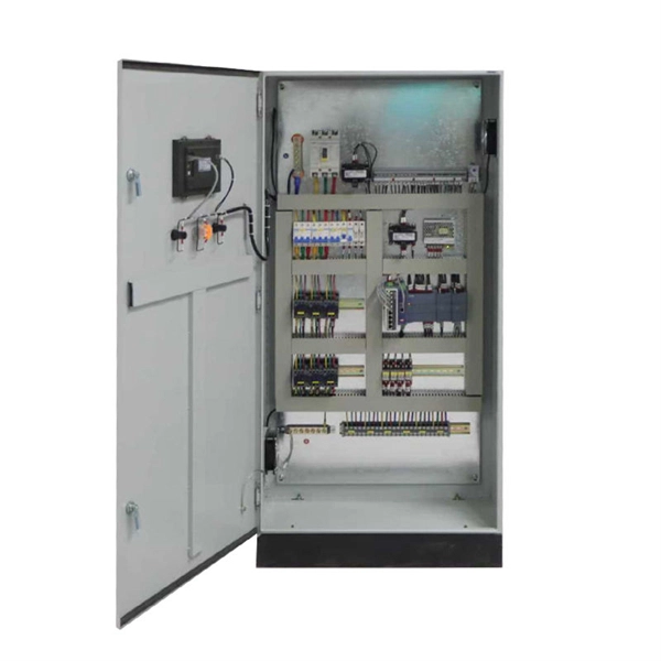
In this paper, various operational factors affecting 100G transmission over G. D fiber-cables are discussed to make the right fiber selection for the long-haul network. Selecting appropriate G. 652 fibre was originally optimized for use in the 1310 nm wavelength region but can also be used in the 1550 nm region. This is the latest revision of a Recommendation that was first created in 1984 and deals with some relatively minor modifications. a number of concatenated cable. G. 92% of. Fiber optic cables are the ultimate technology used in data transfer using light waves. They are classified based on wavelength band, core/cladding size, application, and compliance with international standards such as IEC, ITU-T, and TIE/EIA. In the next sections, the real artwork is putting on. This guide explains the most important ITU-T G. 655—to help you make an informed decision for your project, whether it's a long-haul backbone or a final FTTH drop. In the world of fiber optics, not all glass is created equal. The core of every cable—the optical. Because GPON and XGS-PON are deployed in diverse environments, fiber-containing components such as PLC splitters must be evaluated not only by their standard parameters but also by their sensitivity to bending loss, which is critical for maintaining stable optical transmission. The ITU-T defines.
[PDF]
The Open Systems Interconnection (OSI) model is a developed by the (ISO) that "provides a common basis for the coordination of standards development for the purpose of systems interconnection." In the OSI reference model, the components of a communication system are disting.
[PDF]

Bury cables from 12-36 inches (or 30-90 cm) deep. Where plant life, sidewalks, and other utilities already disrupt earth, it's safer to bury at as little as 24 inches or 60 cm, using protective conduits to limit the likelihood of damaged cables by inexperienced maintenance or. Bury cables from 12-36 inches (or 30-90 cm) deep. These facilities are collectively known as communication infrastructure. Knowing the exact depth of these lines is paramount for anyone planning. The short answer, based on general industry standards and the National Electrical Code (NEC), is that fiber optic cable is typically buried between 24 inches (60 cm) and 30 inches (76 cm) deep. However, simply hitting this depth isn't enough to guarantee your network survives. This. The depth at which cable lines must be buried is governed by a combination of local, state, and national regulations, designed to ensure safety, prevent damage, and maintain infrastructure integrity. These laws typically specify minimum burial depths based on the type of cable (e. 5 meters, balancing protection with installation cost and accessibility. With fiber deployments accelerating in urban and rural areas, understanding these depths is essential for efficient planning and maintenance. In high-load areas such as roads or backbone routes, burial depth can reach 48 inches (120 cm) or more. For broader context on underground.
[PDF]

Based on analysis on the dispersion of the optical system of a MEMS-based VOA, we provide a method to reduce the WDL significantly with minor revision on the end-face angle of the collimating lens. 📦 For purchasing, use the RP Photonics Buyer's Guide for variable optical attenuators. It provides an expert-curated supplier directory, buyer-focused technical background information, and structured selection criteria to support professional procurement decisions. Variable optical attenuators are. An optical attenuator, or fiber optic attenuator, is a device used to reduce the power level of an optical signal, either in free space or in an optical fiber. The basic types of optical attenuators are fixed, step-wise variable, and continuously variable. Optical attenuators are commonly used in. Applications in broadband optical fiber communication system need variable optical attenuators (VOAs) with low wavelength-dependent loss (WDL). What Are Fiber Optic Attenuators? Fiber optic attenuators, also called optical attenuators, are passive. Optical attenuators are categorized based on their attenuation mechanism and adjustability: Fixed Optical Attenuators: These attenuators reduce the signal power by a predetermined value and are used in applications where a constant level of attenuation is required. It works by dissipating a portion of the optical power passing through it, thereby lowering the overall power level. Fiber optic attenuators.
[PDF]

View 18 Communications Equipment Manufacturing company profiles below. There are 88 Telecommunications equipment suppliers in Bolivia as of November, 2025. **** Huawei Technologies. ****. Find detailed information on Communications Equipment Manufacturing companies in Bolivia, including financial statements, sales and marketing contacts, top competitors, and firmographic insights. 06% increase from 2023. 02% of all Telecommunications equipment suppliers in Bolivia are single-owner operations, while the. Market Forecast By Component (Fiber, Transceiver, Switch, Splitters, Circulators), By Technology (SONET/SDH, WDM, CWDM, DWDM, Fiber Channel), By Application (TELECOM, Data Center, Enterprise), By Data Rate (Up To 40 GBPS, Greater Than 40 Gbps To 100 Gbps, Greater Than 100 Gbps), By Vertical (BFSI. Communication Equipment NETWORKS: 1 pc. Seair is proud to have a loyal customer base from big brands. Explore verified Communication importers in Bolivia with customs shipment details, buyers list, and trade data reports for smarter import-export decisions.
[PDF]
Engineered, manufactured, supported and delivered – with pride. We are a British based manufacturer of Copper Cabling Systems, Fibre Optic Products, Racks and Enclosures – deployed in Datacomms, Data Centres, FTTx & Telecom, Broadcasting and Smart Home Applications. British Cables Company is unique by any standards. Not only have we manufactured cables here in Blackley, Manchester since 1895, but also we are evolving into one of the most proficient service providers in the industry. British and proud? Absolutely! The business has always benefitted from. Alker Fibre Optics is an approved supplier direct to the UK MOD and a trusted partner for a number of specialist prime contractors within the military sector. We are always interested to work. Identify and compare relevant B2B manufacturers, suppliers and retailers Max. The company specializes in cabling and IT infrastructure services, highlighting its expertise in fiber optic cable supply and installation. With over 10 years of experience and a fully accredited team, they ensure. For 25 years Copper & Optic has been providing the highest quality electronic manufacturing services. We produce and supply cable and harness assemblies, PCB and fibre optic assemblies, potting and moulding, and automatic testing. Telecom ducting pipe is a non-flexible PVC pipe that carries telecom & data cables. Products are available for purchase online with free 30 day.
[PDF]

This paper is focused on the performance analysis of protection mechanisms utilized in common wavelength division multiplexing-based passive optical networks. Wavelength division multiplexers are fundamental to the functioning and performance of integrated photonic circuits, with applications ranging from optical interconnects to sensing and quantum technologies. Current solutions are limited by trade-offs between channel spacing, crosstalk, insertion. Wavelength division multiplexing (WDM) is a technology for increasing the transmission capacity of optical fiber communications by sending multiple data channels simultaneously through a single fiber, each on a different wavelength of light. The main aim of the proposed research is providing an option of comparing different traffic protection scenarios for advanced optical. Herein, an attention-grabbing and up-to-date review related to major multiplexing techniques is presented which includes wavelength division multiplexing (WDM), polarization division multiplexing (PDM), space division multiplexing (SDM), mode division multiplexing (MDM) and orbital angular momentum. The journey of optical multiplexing began in the 1970s with the introduction of Wavelength Division Multiplexing (WDM), which revolutionized the capacity of optical communication systems. The primary objective of optical multiplexing has been to maximize the utilization of available bandwidth in.
[PDF]

Find low everyday prices and buy online for delivery or in-store pick-up. Find low everyday prices and buy online for delivery or in-store pick-up. Shop products from small business brands sold in Amazon's store. Discover more about the small businesses partnering with Amazon and Amazon's commitment to empowering them. Learn more Made with chemicals safer for human health and the environment. Manufactured on farms or in facilities that protect. 20pcs Transmission Type Photoelectric Switch Optical Interrupter Sensor Opto. OPB825 Opto optical switch, photointerrupter. SA-6C Digital Toslink Optical 4x1 Switch with 3ft Optical Cable and IR Remote Contr. Get the best deals on optical switch when you shop the largest online selection at. Shop for Optical switcher at Best Buy. Networx® Gigabit Ethernet Fiber Media Converter - UTP to 1000Base-SX - ST Multimode, 5. Get fast shipping and top-rated customer service. Price when purchased online Cisco IE-4010-16S12P Ethernet Switch - 12 Ports - Manageable - Gigabit Ethernet - 1000Base-X, 10/100/1000Base-T - 3 Layer Supported - Modular - 16 SFP Slots - Optical Fiber, Twisted Pair - 1U - Rac. Live better. The FOSW-1x1 or 1x2 optical switch is based on opto-mechanical technology with proven reliability.
[PDF]

Urban Areas: 25–40m spacing (concrete poles, 10–12m height)., steel lattice structures). Factors: Cable weight (kg/km) Ice loading (up to 50mm. The Fiber Optic Association, Inc. (FOA) was founded in 1995 to help develop the workforce to build the fiber optic networks to support a rapid expansion in communications and the Internet. The charter of the FOA was to promote professionalism in fiber optics through education, certification, and. to n utral comm. cable R. FO-CS JOINT USE CLIMBING SPACE REQUIREMENTS 51. APPENDIX A - COVER SHEET / TOC 52. RUS DRAWING #PM12 58. CHECK. d suppliers of electrical construction services. They define a minimum baseline of quality and workmanshi for installing electrical products and systems. NEIS® are intended to be referenced in contrac documents for electrical construction ation or liability to users of this publication. Choose the type of pole The basic pole height is 7m and the tip diameter is 150mm. In case of special sections, crossing obstacles or roads or railways, the pole height of 8m, 9m, etc. can be selected. Cables 300 V or less need to be a minimum two feet over the street light. Climbing Space is an unobstructed, vertical space along the side or corner of the pole. In gen-eral, it consists of an imaginary box, 30-inches square, extending at least 40 inches above the highest communications cable or.
[PDF]

In this guide, you will find a chronological description of the fusion splicing process, the principal technical standards, and answers to the real-life questions network engineers and procurement teams may have. TMM P021 OPTIC FIBRE CABLE JOINING, TERMINATION & MANAGEMENT Version 9. Therefore, we will also touch on cost factors, risk management, and best practices in. Fusion Splicing • Splicing is the process of connecting two bare fibres directly without any connectors. • Splicing provide much lower insertion loss compared to fiber connectors that's why Splicing is preferred over the use of Connectors. Fiber mechanical splicing – Insertion loss < 0. 5dB Fiber. What is Fiber Optic Splicing and Why is it Needed? – #1. Ensure Your Splicing Tools are Clean – #2. 56 was approved by ITU-T Study Group 6 (2001-2004) under the ITU-T Recommendation A. 8 procedure on 14 May 2003. The International Telecommunication Union (ITU) is the United Nations specialized agency in the field of telecommunications. By following the step-by-step guide provided, you can effectively perform fusion splicing to maintain high-quality fiber optic.
[PDF]

These invisible highways, consisting of fiber-optic wires connecting landing points, are placed hundreds of metres below the surface of the ocean by cable-laying ships. Submarine cables are laid using special cable layer ships, such as the modern René Descartes , operated by Orange Marine. A submarine communications cable is a cable laid on the seabed between land-based stations to carry telecommunication signals across stretches of ocean and sea. The first. Installing underground fiber optic cables is critical to establishing high speed internet infrastructure that delivers reliable connectivity for businesses nationwide. In this guide, we'll. Photo courtesy of ASN Red buoy markers mark the path of a submarine cable being laid in the ocean. Every day, we send countless emails, take part in video calls, use search engines and streaming services, while seamlessly banking online. These remarkable cables form the backbone of international connectivity, facilitating seamless transmission of vast amounts of information across continents.
[PDF]
