Digital Diagnostic Monitoring (DDM) can monitor parameters of the optical module regularly and generate alarms when parameter values exceed thresholds. By using DDM, you can detect issues early to maintain network stability. When you configure the DDM function, follow these notes. Optical Module Monitoring & Troubleshooting 2026 – network-switch. com Digital Diagnostics Monitoring (DDM), also known as Digital Optical Monitoring (DOM) or Diagnostic Monitoring Interface (DMI), is a standardized feature defined by SFF-8472 that allows network devices to monitor real-time optical. Digital Diagnostic Monitoring (DDM), also known as Digital Optical Monitoring (DOM), is a key feature in modern optical transceivers. It can provide the host with real-time data about the module's internal operating conditions, including parameters such as voltage. Digital Diagnostics Monitoring (DDM) is a feature used in optical transceiver modules that enables you to view real-time information about transceivers, such as optical output and input power. For information about which F5 ® transceiver modules support DDM, see F5® Platforms: Accessories. It is an intelligent function that enables network administrators to monitor the transceiver's operational parameters in real time. DDM is not merely a feature; it is an industrialized standard.
[PDF]
An optical module is a typically hot-pluggable optical transceiver used in high-bandwidth data communications applications. Optical modules typically have an electrical interface on the side that connects to the inside of the system and an optical interface on the side that connects to the outside world through a fiber optic cable. The form factor and electrical interface are often specified by an int. Electrical Interface TypesThere have been multiple variants of the electrical interface of optical modules that have been used over the years. The earliest forms of optical modules had an analog electrical interface. In the transmit dir. Many different forms of optical modulation and multiplexing have been employed in optical modules. The most common modulation technique historically has been or NRZ.
[PDF]
Explore a comprehensive guide to residential electric meter box wiring diagrams, offering clear instructions for safe and efficient installation. A distribution box is the heart of any electrical system. It takes the incoming power and safely distributes it to different circuits throughout your building. However, the key to. Learn how to wire a distribution box step by step! This video shows real on-site footage of electrical installation, demonstrating safe and standardized wiring methods used by professionals. It has three categories: residential, commercial and industrial electrical distribution boxes, all of which play important roles in their respective electrical. Cleaning of the various PXBCM device housings should only be done with power and mains disconnected. A clean dry rag can be used to remove dust. No liquids should be used. Catalog Numbers Catalog Number DescriptionSuffix De- scription Notes PXBCM-MB Meter Base PXBCM-MMS-L09-A Meter Module Strip. full turn-key system solution backed with industry leading reliability and performance. Applications - The minimally invasive retrofit kit enables the opportunity existing remote power infrastructure cross arm, & wiring) providing the total cost of ownership. Failure to strictly adhere to the.
[PDF]
The PL-1000D simultaneously monitors up to 16 fiber strands, eight on the OTDR and eight on the OSA, and operates standalone over dark fiber, lighted fiber, or a third party network without impacting network traffic. The device monitors the entire D. The PL-1000D simultaneously monitors up to 16 fiber strands, eight on the OTDR and eight on the OSA, and operates standalone over dark fiber, lighted fiber, or a third party network without impacting network traffic. The device monitors the entire DWDM C-band spectrum and provides the optical spectrum, OSNR, and OTDR measurements of the fiber. The OTDR locates fiber cut by sending high powered optical pulses into the fiber and creating Rayleigh back-reflections. The returning signals are measured and calculated, indicating the accurate location and intensity of the fault. The OTDR supports GIS (Geographic Information System) using Rest API, enabling precise geographic location of disrupt. The OSA enables the user to monitor the OSNR and optical spectrum of each fiber and shows a full, accurate and detailed picture of the wavelengths used in the fiber. OSADiagram Graphical Display of the OSA, from PacketLight's LightWatch NMS Please contact usfor a quote or further assistance.
[PDF]
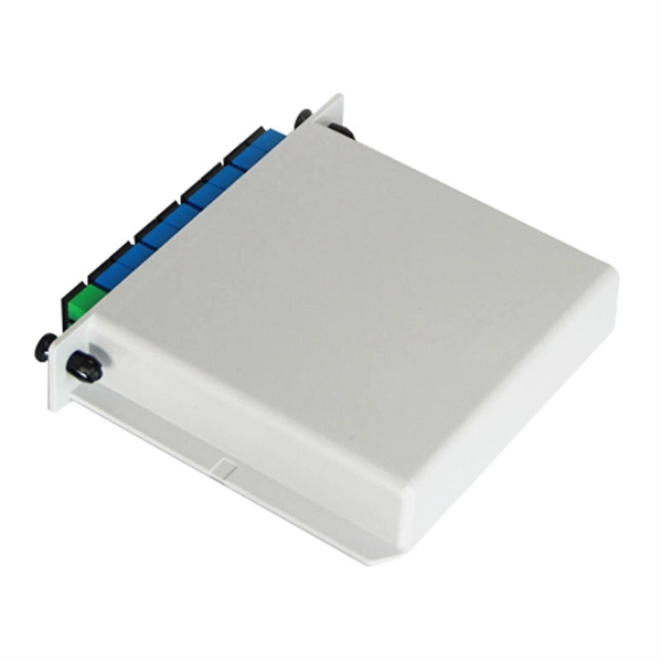
The Patch and Splice Combo Patch Panel is designed to allow both the patching and splicing of fiber optic cable all in one unit; these particular units have fiber termination panels in the upper slide out shelf and splice trays in the lower shelf. NG4access ® Cabled Modules available in all module sizes and fiber counts up to 864 fibers NG4access ® Splice Tray Four sizes of interchangeable Propel fiber pass-through adapter packs provide the breadth of capabilities for virtually any configuration. Four sizes of interchangeable Propel fiber. Cisco is introducing a family of fiber management solutions with a debut of SMF and MMF patch panels. The panels will enable Cisco's customers to facilitate breakout connectivity agnostic of the data rate. The Cisco® solution of panel and cable assemblies offers versatile solution for any breakout. Our fiber patch panel offers options for flexible cable management and seamless integration with various cassettes and fiber optic accessories. Allowing full front access for network. Foss FP-series front patch panels are made with the highest accuracy for precise fitting. All panels are tested according to both our own quality measures and international standards before they are sent to customers. Similarly, the ABS High Density Shelves bring a new level of access, convenience, and security to its Fiber Splice Shelf, enabling quick and easy fiber splicing and connectivity for rack mount applications.
[PDF]
Follow the described steps to factory reset an IBM Brocade switch running FOS 7. Run firmwarecleaninstall on each CP or switch After firmwarecleaninstall, all passwords, such as root, admin, factory and user are cleared (set to the default value). Before installing a new software version and RCF files, you must erase the current switch configuration and perform basic configuration. Log in to the switch as an administrator. The system is halted flushing ide devices: hda Power down. Display information about switches in the fabric. Display how long the switch is running, number of connected users and the system load for the past 1, 5 and 15 minutes. Display or set date and time (This is Readonly if NTP is. This video will demonstrate clear procedure of an interface and ASIC counters on Brocade B-Series Switches and Directors Welcome to Dell Technologies Connectrix Brocade How To Series. WARNING: This is a.
[PDF]

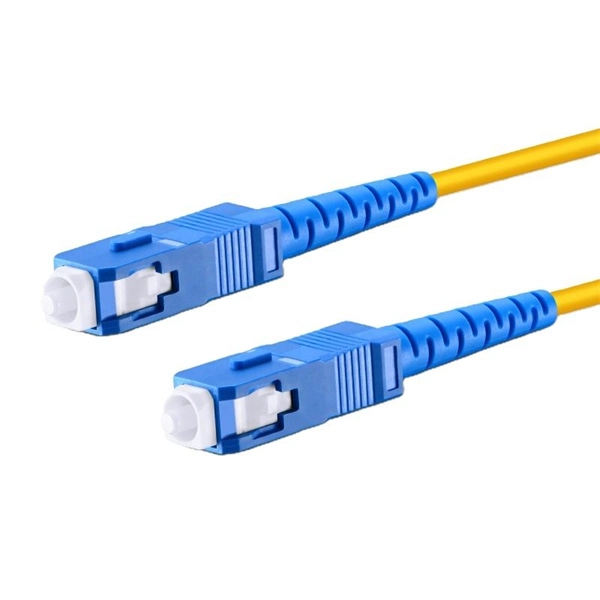
This guide will walk you through the most common fiber connector types, explaining their characteristics, advantages, and typical use cases. An optical fiber connector is a device used to link optical fibers, facilitating the efficient transmission of light signals. An optical fiber connector enables quicker connection and disconnection than splicing. Whether you're planning an FTTH deployment, upgrading a data center, or working in telecom infrastructure, this guide will help you make informed decisions. This guide provides a fully updated and industry-ready overview of LC fiber optics, explaining the origin and design of LC connectors, their key features, and the complete ecosystem of LC-based products used in modern networking. It covers LC connectors, LC patch cables, uniboot designs, armored. Fiber connector types LC, SC, FC, ST, MTP, and MPO are widely used in past and present. What are the differences between them? Who is the most popular one? Find the answer in the article. What is a Fiber Connector? The optical fiber connector is a kind of detachable passive optical component used. The answer often lies in tiny but mighty components called LC connectors. There have been many types of connectors developed for fiber cable. Single mode networks have used FC or SC.
[PDF]

This guide will explain their functions, discuss the role of single-mode LC connectors in modern fiber optic systems, and present the logic for their adoption on a broader scale. Proper connection of fiber optic cables is essential to harness these benefits fully, as even minor errors can lead to significant performance issues like signal loss. This article will guide you through the necessary tools, materials, and methods on how to connect fiber optic cables effectively. Fiber optic internet delivers blazing-fast speeds and reliable connectivity, making it a top choice for modern homes and businesses. In this guide, we'll walk you through how to. In this article, we'll explain how to connect multiple Ethernet switches using fiber optic cables and the equipment required for this to work. Network topology refers to the way in which the links and nodes of a network are arranged in relation to each other. There are also fiber-to-fiber versions that translate between different fiber types, wavelengths, or distances. Common families support 10/100/1000 Ethernet and. This is where single-mode fiber optics comes in. Single-mode fiber is being viewed as the backbone of enterprise connections, and it is used to facilitate all 400G solutions and real-time AI solutions/applications, due to its ability to transmit data over long distances with minimal signal loss.
[PDF]

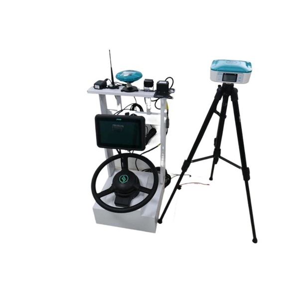
Based on the need for real-time sag monitoring of Overhead Power Lines (OPL) for electricity transmission, this article presents the implementation of a hardware and software system for online monitoring of OPL cables. OptiSystem is an optical communication system simulation package for designing, testing, and optimizing virtually any type of optical link in the physical layer of a broad spectrum of optical networks, from analog video broadcasting systems to intercontinental backbones. A system-level simulator. Enhance your OTDR training and demonstrations with the portable Fiber Lab MSP. This all-in-one solution simulates P2P, FTTx, and Cell Tower fiber spans in a single unit, while including over 20km of fiber, good/bad splices, 1xN splitter, and reflective connectors. WHY CHOOSE THE FIBER LAB MSP? When. OCSim modules have been proven to provide accurate simulations. The modules which are continuously upgraded are and laboratory simulation experiments. The mathematical model based on differential equations and the methods of. This repository is a Python-based framework to simulate systems, subsystems, and components of fiber optic communication systems, for educational and research purposes. Several digital modulations available (M-PAM, square M-QAM, M-PSK, OOK) to simulate IM-DD and coherent optical systems.
[PDF]

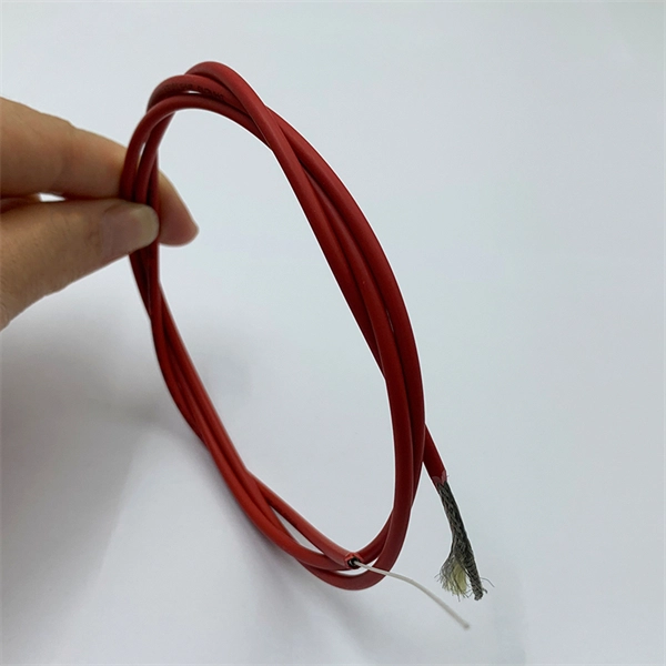
This article unpacks the technologies powering this leap (silicon photonics, advanced modulation, and co-packaged optics), compares deployment paradigms, and delivers a tactical upgrade roadmap that balances performance, cost, and scalability. OFC 2025 made one thing clear: The transition to Co-Packaged Optics (CPO) switches in data centres is inevitable, driven primarily by the power savings they offer. From Jensen Huang showcasing CPO switches at GTC 2025 to a wide range of vendors demonstrating optical engines integrated inside ASIC. AI and cloud traffic surged, driving inter-data-center bandwidth purchases up 330% from 2020 to 2024. By 2025, operators moved past 400G, with 800G becoming the mainstream, and early pilots pushing into 1. 6T 224 Gb/s PAM4 links. Yet supply has lagged demand. In early 2024, primary North American. With 400G modules now the baseline, 800G adoption is surging—especially across AI and hyperscaler environments—while 1. 6T modules edge closer to reality. With 9 years' experience in semiconductor technology, Martin is currently involved in the development of technology &. Active Electronic Cables (AECs) and Active Copper Cables (ACCs) will gradually gain market share at the expense of passive Direct Attached Copper (DACs). AECs and ACCs offer longer reach and are much thinner than DACs. Another advantage of ACCs is lower latency – critical for AI clusters.
[PDF]