
Single-mode optical splitters are optimized for single-mode optical fiber, while multimode optical splitters are tailored for use with multimode optical fiber. An Optical Splitter, also known as a beam splitter, is a passive optical device that divides a single input optical signal into two or more output signals. Conversely, it can also combine multiple signals into one. Its primary role is in Passive Optical Networks (PON), which are the foundation of. This guide demystifies fiber optic splitters, explaining their design, operating principles, types, key specifications, and real-world applications. It can distribute the optical energy transmitted through a single fiber to two or more fibers in a predetermined ratio or combine the optical energy from multiple fibers into one fiber. “Passive” means it needs no. You use optical couplers and splitters to split or join signals in fiber networks. For example, optical splitters send light to many output ports. This lets you connect more users to one network terminal. There are different types of fiber optic splitters available, with two of the most common being Fused Biconical Tapered (FBT) splitters and Planar Lightwave.
[PDF]

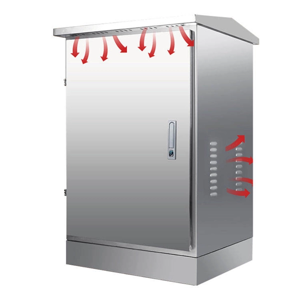
Primary: The main distribution panel, supplies power from the transformer. The terms primary, secondary, and tertiary distribution boxes are relative. Let's make an example for clarity: A newly constructed residential area introduces a 10kV power line to a substation. From the transformer's low-voltage side (0. Spot Networks are used for customers with the highest reliability requirements. This configuration connects two or more transformers (fed from at least two. A complete set of products can form a complete construction electricity three-level protection system, to achieve the purpose of one machine, one gate, one protection. The secondary box is designed with inside and outside doors and sprayed with plastic. Safe and beautiful, waterproof box top. These smaller breaker panels, also known as sub-distribution boards, are commonly used to provide power to secondary circuits within a building. Understanding the components and wiring configuration of an electrical sub panel is essential for safe and efficient electrical installations. In this. ACS takes the basic idea of zone wiring and combines it with pre-cut, pre-tested cable and plug-in connectors, to provide power and telecommunication systems that can be installed under raised floors (The Intelligent Floor), or in accessible ceilings (The Intelligent Ceiling). installed under.
[PDF]

Network segmentation with switches involves dividing a network into smaller, isolated segments to enhance security, improve performance, and simplify management. Learn how to configure a switch for network segmentation effectively by using VLANs, subnetting, and access control lists (ACLs). You may. to communicate with each other. VLA h or complete physical network. When you physically separate a network, the devic s are assigned to a switch port. However, when a network is separated using VLANs, the devices are logically separated by n of the VLANs is not mandatory. VLANs can also extend. Explore how Versitron single fiber media converters support fiber optic packet forwarding, VLAN tagging, signal amplification, and robust network segmentation—ideal for scalable and secure data infrastructure. Setting up a VLAN on a fiber optic switch is very similar to setting up on any other type of switch, but it's important to make sure the switch supports VLAN functionality. The. By segmenting a network into VLANs, you will increase usable network bandwidth, resources, and performance through the reduction of broadcast traffic. Routers also break up broadcast domains. Routers operate at Layer 3, forwarding packets based on IP addresses, not MAC addresses. A router will. Step-by-step instructions for configuring VLANs using network hardware. Allocate unique segment identifiers directly through your device's interface to minimize broadcast domains and reduce.
[PDF]

Mainly 9steps: Step 1: cut cable with cutting machines in lengths Step 2: put the connector spare parts on the cable Step 3: Strip cable jacket, coating till bare fiber, and make all parts in ready Step 4: Insert fiber into ferrule, glue dispenser and heat oven Step 5:. Mainly 9steps: Step 1: cut cable with cutting machines in lengths Step 2: put the connector spare parts on the cable Step 3: Strip cable jacket, coating till bare fiber, and make all parts in ready Step 4: Insert fiber into ferrule, glue dispenser and heat oven Step 5:. Learn how to make a fiber optic patch cord step by step, from preparation to testing, for reliable high-performance connections. Most guides on making fiber optic patch cord 1 s feel incomplete. They often focus on the final assembly steps, leaving the foundational stages a mystery. From cable cutting to connector assembly and testing, you will gain valuable insights into the production of. Fiber optic patch cords and Pigtails are very important passive fiber optic components in fiber optic networks. Use the fiber optic cleaver to cut the. This document describes the installation and use of the mode-conditioning patch cords listed in Table 1. A mode-conditioning patch cord is shown in Figure 1 IEEE 802. 3z-compliant optical fiber assembly consisting of a single-mode fiber permanently coupled off-center to a 62. 5-micron multimode.
[PDF]
However, by using heat shrink tubing, it's possible to establish a tight, reliable seal around cables and wires, essentially providing a waterproof finish. This helps deter the risk of water-induced damage, helping to extend the durability and lifespan of your electrical systems. Outdoor junction boxes are exposed to harsh environmental conditions, including rain, snow, UV radiation, and fluctuating temperatures. Without proper weatherproofing, moisture can penetrate the enclosure through cable entries, mounting holes, or compromised seals. The consequences of poor. Heat shrink tubing is commonly used for waterproofing electrical connections, particularly in applications where exposure to moisture is a concern. Here's how waterproofing through heat shrink works: Selecting the Right Tubing: Choose heat shrink tubing that is specifically designed for. Heat shrink tubing is an indispensable thermoplastic sleeve used in wiring and cable management. It is a “must-have” insulating tool for electricians and engineers, providing reliable protection and a secure seal around wires and connectors. The outer layer is typically made of a durable, flexible polymer material (often polyolefin), which is designed to shrink when exposed to heat. This simple technology typically involves a polyolefin sleeve that has been expanded and then set with a memory to shrink back to its original, smaller size when.
[PDF]

This guide covers the critical steps, from selecting the right electrical cable tray and performing accurate cable fill calculations to managing a safe cable pull through and ensuring all bonding and grounding requirements are met. But before you lay the first tray or clamp down a single cable, you need a solid plan. This guide breaks down the process step by step. Plan the Route Before You Drill No installation should start without a plan. For licensed electricians, mastering these principles is essential. Cable tray installation implies the construction of an electric road that will be safe. In order to get it right, installers are supposed to adhere to a plan that ensures that wires are kept cool and the building is stable. The beginning of success is to review the Bill of Quantities (BOQ) so that. Cable tray systems provide a safe, organized, and flexible method for supporting insulated conductors and cables in commercial and industrial electrical installations. When properly selected and installed, cable trays simplify routing, improve accessibility, and support future expansion while. Proper installation of cables in trays is critical for maintaining an efficient and safe electrical system. This process is integral to determining the optimal arrangement and configuration of cable trays, which are essential for routing and supporting electrical cables within buildings and.
[PDF]

The following are the precautions for the use of Gigabit optical transceivers and 10 Gigabit optical transceivers, some common fault causes, and corresponding troubleshooting methods and solutions. Avoid damage. In the formation of modern networks, optical modules are essential equipment, of which Gigabit optical modules and 10 Gigabit optical modules are popular because of their high speed and stable transmission rate and wide applicability. However, the failure of optical modules is a common problem. 10G SFP+ optical modules remain one of the most widely deployed transceiver solutions in data centers, telecom networks, enterprise switching, and cloud-scale architectures. Their compact size, low power consumption, and versatility across multimode and single-mode fiber make them a critical. Gigabit optical transceivers and 10 Gigabit optical transceivers are an essential part of modern network communication, but they will inevitably encounter some failures during use. This article dives into technical specifications, real-world usage scenarios, selection criteria, and. Single-fiber bidirectional (BIDI) optical modules must be used in pairs. For example, SFP-10G-BXD1 must be used with SFP-10G-BXU1. Cisco XFP Module Main features of the Cisco XFP Module include:.
[PDF]
Tilt sensors are devices that measure the tilt or slope of an object with respect to a reference. Fibre Bragg Grating (FBG) tilt sensors are a specific type of tilt sensor that utilizes the principle of Bragg's law in fiber optics to measure tilt angles. The tilt sensor is composed of two cylindrical floats suspended in water, connected with FBG. When the external environment causes the tilting of the sensor. Abstract—A surface-mounted tilt sensor was designed and fabricated to measure the inclination angle of engineered structures or slopes in two directions. In a FBG tilt sensor, the optical fibre is. We demonstrate a new concept for an all-fiber inclinometer based on a tapered fiber Bragg grating (tFBG) in a fiber ring laser (FRL) with the capability of measuring the tilt angle and temperature simultaneously.
[PDF]
Discover 30 everyday pigtail hairstyle ideas to add a fun, stylish touch to your daily look. From classic to modern twists, this gallery has something for everyone. Wavy Bubble Braid Pigtails 2. Half Pull Through Pigtail Braid 5. From high ponytails with scrunchies to space buns, we keep looking to the past for inspiration. One hairstyle that definitely reminds us of the old days is pigtails. When you think of pigtails, you might remember wearing them a lot as a kid, especially on picture day. Even though pigtails are seen. These 34 adult pigtails styles are reminiscent of the schoolgirl classic but with chic twists that work for different hair types. The past few years have served up tons of throwback hairstyle nostalgia. High Ponytail Pigtails The classic high ponytail pigtails never go out of style and look great on long hair. Create this look by dividing your hair into two sections and securing it with an elastic band at the crown of your head. When it comes to versatile and timeless hairstyles, pigtails undoubtedly top the list. Whether you're looking for a playful look for a casual day out or a chic twist for an evening event, pigtails can be styled to match any occasion. Part your hair down the middle and instead of combing up the entire section, just comb the top portion of the hair back and secure with an elastic. For added oomph, leave out a few.
[PDF]

Choosing the right electrical junction box size is crucial for safety and code compliance in your US projects. This guide helps you determine the correct dimensions based on wire fill capacity, device requirements, and installation environment, ensuring a safe and efficient electrical system. Choose the right box based on environment (indoor/outdoor), load capacity, and durability. Check for proper IP/NEMA ratings and material quality. Ensure safe placement: install in dry, accessible areas with good ventilation and at appropriate height (typically ~1. Practice good wiring: secure. Summary: The National Electrical Code explains the Maximum Number of Wires that can be installed into a box, otherwise known as Box Fill. This code is based upon the type of box, wires, wire sizes, wire clamps and conduit fittings. Adjustments are made for the ground wire as you will see in the. A distribution box, also known as a distribution board, electrical panel, or breaker box, is an enclosure that houses electrical components responsible for distributing electricity throughout a building. It receives power from the main electrical supply and divides it into separate circuits, each. These Tables of Electrical Service Entry Cable Sizes, Electrical Circuit Wire Diameters, Circuit Ampacity, Allowable Voltage Drop, & Wire Size Increase based on Run Length assist in determining the electrical service size or other required electrical wire sizes at buildings.
[PDF]

Step-by-step guidance on installing an electric meter box safely—site prep, clearances, mounting height, wiring, grounding, permits, and code compliance explained. Learn safety tips, wiring steps, troubleshooting, and when to call a pro. An electric meter box measures how much electricity your home uses. It helps the utility company give you the right bill. If you're setting up a new one or replacing an. It is a box that is hard to access, fails inspection, or cannot support future loads and upgrades. Then I fix the box securely, route and terminate cables neatly, seal. An electric meter box looks simple from the outside. It is just a box on a wall. But the way it is installed affects safety, compliance, maintenance, and even how fast you can get utility approval. A sloppy installation can create small problems that stay hidden for years. Installing an electric meter box might seem like a job for professionals only—but with the right knowledge, it's a task many homeowners. In this guide, we will break down the key elements involved in connecting the main power supply to your home, providing a clear path for a successful setup. We will focus on the critical parts of the system, from basic components to step-by-step assembly procedures. The Owner/Contractor is required to fix instal electric transmission or distribution system. OUC may remove any such equipment installed between the transformer to the meter and may require the Customer, as.
[PDF]
