How to Install a Fibre Connector into a Patch Panel (Easy fibre optic connector installation) How to Install a Fibre Connector into a Fibre Optic Patch Panel. How do you install fibre optic connectors?. Connecting a fiber patch panel to a switch is a critical step in setting up a fiber optic network. There are different types of connectors. In today's high-performance networks, fiber optic patch cables are the lifelines that ensure smooth data flow across switches, servers, and routers. Even the most advanced optical transceivers can only perform at their peak when paired with properly installed, clean, and precisely managed fiber. Choose an SFP module based on the fiber optic cabling that will be connected to the network switches. SFP transceiver modules almost always require two fiber optic cable strands. A Fiber Patch cord connects two devices. You plug it into a switch, router, or patch panel. It's ready to use out of the box. A pigtail is for splicing. You fuse it to a. With a railroad switch (patch panel), the train (data) can travel from A to B, C and even more destinations, otherwise it can only go from A to B, or C to D. This article, What Is a Patch Panel Used for?, has explained it thoroughly.
[PDF]
The applicable subheading for the fiber optic panel/chassis and fiber optic patch tray, will be 9403. 8040, Harmonized Tariff Schedule of the United States (HTSUS), which provides for “Other furniture and parts thereof: Parts: Other: Other; Of metal. ” The rate of duty will be free. Item 1, part number LCXE-M1RU-BLK, is described as a fiber optic chassis with the capabilities of holding twelve fiber optic cables. The panel is produced from cold rolled. The merchandise is fiber optic patch panels that provide a consolidated point of demarcation for optical terminations, connections and cross connections within a passive, fiber optic network. They are designed to be mounted onto a wall or rack. All fiber optic patch panels will consist of the. Find verified buyers and sellers of Fiber Optic Patch Panel in 180+ countries along with their valid phone numbers and email ids. The top 3 Buyer countries for HS Code 851770 are “ PHILIPPINES ”, “ INDIA ”, “ PAKISTAN ”,. com if you have any questions or special project needs. The panel is produced from cold rolled. In the United States, customs duties imposed on imports from Asian countries have increased costs for Internet service providers and telecommunications companies, in many cases delaying infrastructure expansion and maintenance projects. In Latin America, several countries have adopted tariff.
[PDF]

Compare fiber optic and copper Ethernet cables across speed, distance, cost, installation difficulty, and use case metrics. Use the interactive scenario selector to find the right medium for your specific network — all processed locally in your browser. PoE Required?. The core difference between fiber optic and copper cables lies in how they carry data. One uses light, the other electricity—and that distinction shapes everything from speed to signal integrity. Fiber optics transmit data as pulses of light through ultra-thin strands of glass or silica. Both technologies can deliver high-speed connectivity, but they behave differently under real-world constraints such as. However, the exponential growth in data demand has positioned fiber optic technology as the superior alternative for performance, scalability, and future-readiness. This article provides a detailed technical comparison between fiber optic and copper cables, offering a clear perspective for. Fiber optic tends to be the more premium solution, while copper wiring is far more common, but why is that? What are the differences between these two cable types, and why might you want to pick one over the other? Here's everything you need to know about fiber vs. copper cables, to help you pick. Several factors are converging to drive the switch from copper to fiber – and cost is a big one. A recent investor presentation by AT&T claimed that fiber was 35% less costly to maintain than copper.
[PDF]

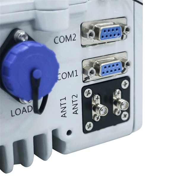
This blog article entry considers the merits of choosing which of various low loss RF coaxial cables to use for IoT, LTE or LORA wireless applications where an external antenna is used to connect to router, gateway or terminal. The choice looks deceptively simple—pick a length, screw it on—but RF engineers know the truth: every extra meter quietly eats away at your link budget, especially once you cross 2 GHz. It's not just about length; the cable type, connector quality, and even mounting environment make a measurable. Audio generated by DropInBlog's Blog Voice AI™ may have slight pronunciation nuances. In this article, we will consider cables such as RG174, RG58, RF195. The cheap connectors have inferior dielectric between the poles as well as poorer grades of metal. The dielectric won't handle high power (KW range) as well and the center pin can more easily shift causing impedance problems if they are moved frequently. RF connectors are usually used with coaxial cables. They are designed to maintain the shielding that the coaxial design offers. The better and newer. Besides the wide range of RF connectors, Telegärtner also provides a considerable range of suitable coaxial low loss cables. Using this one-stop shopping option at Telegärtner makes your purchasing process even more efficient. The main use of low loss cables are all kinds of wireless applications.
[PDF]

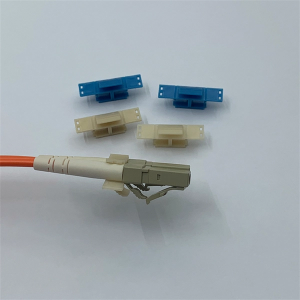
This article will compare waterproof connectors and non-waterproof connectors, highlighting their key differences, advantages, and best use cases in FTTH deployments. 🔍 What Are Waterproof Connectors?. In modern fiber optic deployments, one of the biggest challenges is ensuring stable and long-term connectivity in harsh outdoor environments. The comparison is typically triggered during outdoor deployments, edge network extensions, or hybrid indoor–outdoor transitions where connectors may be exposed. This is where Ruggedized Fiber Optic Connectors come in. Whether you are connecting a Remote Radio Unit (RRU) for Ericsson, Nokia, or Huawei, or setting up a harsh-environment sensing network, choosing the right waterproof interface is critical to preventing signal loss and network downtime. In. In today's fast-paced digital world, the choice of fiber optic connectors can significantly impact performance, reliability, and longevity of networking solutions. Among the varieties available on the market, waterproof fiber optic connectors have emerged as a superior option for many applications. In this blog, we will focus on comparing the performance of Mini LC.
[PDF]
Dual door fiber enclosures provide our highest level of distribution panel security. They give you the option to separately lock the network and distribution doors for more control over panel access. The second doo.
[PDF]

A typical fiber connector (the plug-and-socket type you'd find on patch panels) adds around 0. 5 dB of loss per connection. Higher-quality connectors under ideal conditions can get down to about 0. Attenuation in fiber optics is the gradual loss of light signal strength as it travels through a fiber cable. It's measured in decibels per kilometer (dB/km), and it determines how far a signal can travel before it becomes too weak to read. A standard single-mode fiber operating at 1550 nm loses. Optical Signal Attenuation is the single greatest factor limiting the distance and performance of your network. Understanding it is crucial for anyone involved in data centers, telecommunications, or enterprise networking. This guide will demystify signal loss, explore its causes, and show you how. F iber optic networks rely on the efficient transmission of light signals to deliver high-speed data over long distances. However, various factors can cause signal degradation, leading to performance issues and reduced network reliability. Fiber optic signal loss, also known as attenuation, occurs. Home1 / Blog2 / fiber optic3 / How to Fix High Attenuation & Signal Loss in Fiber Optic Networks. Signal loss in Fiber Optic networks can make data slow. High attenuation makes your system not work well. You may see slower speeds and less steady connections when signal loss goes up. Things like impurities in the fiber core and reflections at the core-cladding edge cause this drop.
[PDF]

Practice good wiring: secure grounding, neat cable management, proper insulation, and correct wire gauge and breaker size. Include protection devices like breakers, fuses, and surge protectors—each circuit should have its own protection. Comply with standards: Follow NEC, IEC . An electrical panel box, also known as a breaker box or a distribution board, is a crucial component of any electrical system. It serves as a central hub for distributing electricity throughout a building, ensuring that power is delivered safely and efficiently to all the required locations. In this video, we'll walk you through the process of wiring a home distribution box with a detailed connection diagram. Whether you're an electrician or a DIY enthusiast, this guide will help you understand the basics of home electrical distribution. more Welcome to our channel! In this video. Choose the right box based on environment (indoor/outdoor), load capacity, and durability. Check for proper IP/NEMA ratings and material quality. Ensure safe placement: install in dry, accessible areas with good ventilation and at appropriate height (typically ~1. It involves connecting wires and components properly, to ensure safety and efficiency. Good wiring is vital to prevent electrical hazards and keep appliances, lights, and other electrical devices functioning well. It receives power from the main electrical supply and divides it into separate circuits, each.
[PDF]
You use a fiber distribution panel to keep fiber optic cables organized. This panel helps you manage cables in your network. The panel protects connections from dust and water. It also shields them from changes in temperature. With the growth of the fiber industry, a wide array of fiber optic patch panels have been developed to fit the many needs of these varying environments. If you already know what your project requires, check out our complete Fiber Patch Panel selection. What is a Fiber Patch Panel? Fiber optic patch. A fiber patch panel is a mounted enclosure—either rack-mounted or wall-mounted—used to terminate, manage, and interconnect multiple fiber optic cables. It acts as a hub for organizing splices and patch cords, streamlining fiber management and preserving signal integrity. You use this device to connect and separate fiber cables. It lets you reach each fiber connection easily.
[PDF]
Coherent optical module refers to a typically hot-pluggable coherent optical transceiver that uses coherent modulation (//) rather than amplitude modulation (RZ//) and is typically used in high-bandwidth data communications applications. typically have an electrical interface on the side that connects to the inside of the system and an optical interface on the side that connects to the outside world through a fiber optic cable. The technical details of coherent op.
[PDF]

This guide is intended to present the fundamentals of power system design for commercial and industrial power systems. A distribution board, also known as a panel board or breaker panel, is an enclosure that houses electrical components such as circuit breakers, fuses, and busbars. Its primary function is to distribute electrical power from a main supply to various circuits while providing protection against. These Distribution Boxes enable decentralized installation of the electronics close to the load. The range of applications extends from pure energy distribution in buildings to building automation and through to industrial plants. SMART DISTRIBUTION BOXES FOR FLEXIBLE BUILDINGS. It is a vital part and central hub of any electrical system. Whether it's a home, office, or factory. Electrical distribution system design is a critical aspect of industrial facility engineering that determines how electrical power is delivered from the utility service to end-use equipment. A well-designed distribution system provides reliable power, adequate capacity, proper protection, and. In industrial power distribution systems, cable distribution boxes (also known as power distributor boxes, distribution electrical boxes, or electrical power distribution boxes) are the core hub of power transmission, branching, and protection. Its layout directly affects the efficiency of the.
[PDF]

This manual details the installation, operation and maintenance instructions for type JBDB Junction/Terminal Box (flameproof). This product is ATEX and IECEx certified to meet the requirements for hazardous location equipment. Safely conduct, connect and distribute energy in hazardous areas with R. STAHL's terminal boxes. We offer bespoke, custom-made terminal boxes and terminal box combinations, as well as standard products with short delivery times. Our products are certified for installation technologies all over the. trait or landscape orientation in temperatures ranging from -60 oC up t +90 oC. For terminal and entry device configuration options please see ove er configurations c nal types and ter Attestation of Conformity and instruction. ta g a screwdriver with a #2 Phillips Head, a Standard Slotted or Robertson style head, remove the cover screws. Secu y fasten the enclosure to the mounting location, using up to a 1/4” (M6) diameter steel bolt and washer. It combines and supersedes two previous FAA ACs on this topic: AC 150-5360-13, Planning and Design Guidelines for Airport Terminal Facilities, and AC 150/5360-9, Planning and Design Guidelines for Airport. ABS Plaza 16855 Northchase Drive Houston, TX 77060 USA These Guidance Notes provide ABS recommendations for the design and construction of cable trays and junction boxes. These Guidance Notes are applicable to fixed and floating offshore structures as well as drilling units. These Guidance Notes.
[PDF]

This guide covers everything: what fiber optic pigtails are, how they differ from patch cords, which connector and polish type to specify, how to choose between mechanical and fusion splicing, and the real-world applications where pigtails are the right call. In this guide, we cover the basics of fiber optic splicing, how to perform splicing using two different methods, and finally some best practices to perform good fiber splicing. What is Fiber Optic Splicing and Why is it Needed? – #1. Whether you're building out an ODF. Think of a fiber optic cable splice as the seamless stitching that keeps data flowing through the delicate threads of a network—like a master tailor joining fabric with precision. Whether repairing a broken cable or extending a fiber run, fiber optic splicing ensures light signals travel. Fibre optic splicing is an essential skill in the world of modern telecommunications, offering a reliable method to connect optical fibres for seamless data transmission. As the demand for high-speed internet and robust communication networks continues to grow, learning to splice fibre optics is. In this guide, you will find a chronological description of the fusion splicing process, the principal technical standards, and answers to the real-life questions network engineers and procurement teams may have. Therefore, we will also touch on cost factors, risk management, and best practices in.
[PDF]