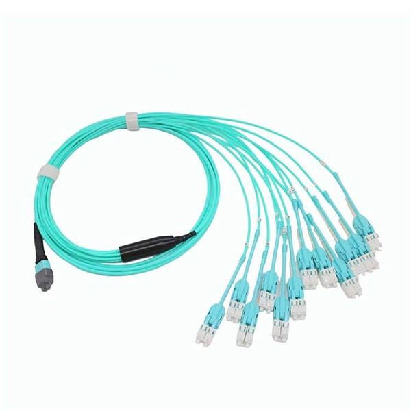
In practice, there are two main ways to terminate fiber optic cable: using a connector to join two fibers to create a temporary, removable joint, or using splicing technology to permanently join two bare fibers directly. Either. Terminating fiber optic cables essentially means putting connectors on fiber optic cable so that you can connect the cable to various devices or network components. Think of it as the equivalent of connecting the dots in a complex puzzle; without proper termination, the whole system can break down. Fiber optic networks are the backbone of modern communication systems, enabling high-speed data transfer and reliable connectivity. When deploying fiber optic cabling, one of the most critical decisions is how to terminate the fiber—either by splicing or using connectors. The process of fiber optic cable termination is the essential act of connecting fiber optic cables to devices, patch panels, or other cables to enable. This Applications Engineering Note explains how different optical fiber termination methods impact the optical performance of telecommunications systems. Optical fiber cabling systems support various communications technologies that use digital as well as analog signaling. This involves either installing a connector or creating a splice to establish a reliable connection point for the optical signal.
[PDF]

Common methods of protecting busbars include overcurrent-based interlocking schemes, overcurrent-based differential protection, high-impedance differential protection, and percentage differential protection. Interlocking and overcurrent differential protection can be implemented with any suitable. DEFINITIONS. IV EXECUTIVE. Busbar Differential Protection Definition: Busbar differential protection is a scheme that quickly isolates faults by comparing currents entering and leaving the busbar using Kirchoff's current law. Current Differential Protection: This protection method connects CT secondaries in parallel and. Busbars play an important role in power transmission and distribution. They are employed as a central distribution point for all feeders. The problem is that the busbars. Busbars have typically been left without dedicated protection, from the following reasons: It is a fact that the risk of a short circuit happening on modern metal clad equipment is insignificant, but it cannot be completely dismissed. Nevertheless, the damage resulting from one short circuit may be. 25 kV insulation is required. These heat-shrinkable tubes for straight and bent busbars are extremely flexible, allowing them to be easily positioned on busbars and quickly instal ed using a gas torch or oven. They have a high expan-sion ratio, so each size of tubing fits a range of busbar sizes.
[PDF]

This article covers various types of protective relays, such as overcurrent, directional, and differential relays, highlighting their operating characteristics and applications in electrical systems. Different Types of Protective Relays What is a Protective Relay?. Protective relays and devices have been developed over 100 years ago to provide “lastline”of defense for the electrical systems. They are intended to quickly identify a fault and isolate it so the balance of the system continue to run under normal conditions. The selection and applications of. Protective Relay Definition: A protective relay is an automatic device that senses abnormal conditions in electrical circuits and triggers actions to isolate faults. Types of Protective Relays: Protective relays are categorized by their mechanism (electromagnetic, static, mechanical) and function. A protective relay is an intelligent electrical device designed to detect faults in power systems and initiate corrective actions such as tripping a circuit breaker. : 4 The first protective relays were electromagnetic devices, relying on coils operating on moving parts to provide detection of abnormal operating conditions such as. Relion protection and control relays for several application reduce complexity.
[PDF]

Learn how to install a fiber optic termination box step-by-step for FTTH projects. Covers mounting, splicing, routing, labeling, and testing for indoor/outdoor use. Installing a fiber optic termination box is one of those jobs that looks simple on paper. A fiber termination box is the standard instrument used in fiber optic networks to connect, secure, and protect optical fibers at the terminating point. Proper installation and maintenance of FTBs are essential to ensure the reliability and performance of the network infrastructure. Before. FTTP or fiber To The Premises applications have reinforced the importance of reliable and stable fiber optic terminations. Good quality fiber laying and termination systems help achieve minimal back reflection and low signal loss. They also feature resistance to moisture, impact, chemical exposure. New pole mount bracket YK-SX, made by Jera line, to attach and reattach the fiber optic termination boxes, during aerial fiber deployment. No more time losses on reattaching the termination box from the pole. It serves as a critical junction point within a network, providing a centralized and secure. A Fiber Termination Box, also known as a Fiber Distribution Box, is a crucial component in fiber optic networks. FTBs play a vital role in ensuring the.
[PDF]

Look for boxes made from durable, weather-resistant materials. Plastic or fiberglass options often provide better waterproofing than metal ones. If you're unsure, consult with a professional or check product specifications to understand the waterproof ratings. Next, inspect the. A waterproof distribution box is an essential component used in various electrical installations to protect wiring and equipment from water damage. Typically constructed from durable, corrosion-resistant materials, these boxes are designed to withstand exposure to moisture and harsh environmental. What are the effects of chemicals on waterproof distribution boxes? The primary effects of chemical exposure on a waterproof electrical box include material degradation, stress cracking, and the loss of sealing integrity. Depending on the material (ABS, Polycarbonate, or Stainless Steel), contact. What is the difference between thermoset and thermoplastic materials? You can find distribution boxes made from various distribution box materials such as steel, aluminum, PVC, polycarbonate, high-density polyethylene, and thermoset plastics like SMC. These enclosures serve not only industrial applications but are also crucial for residential and commercial settings.
[PDF]
Optical components including laser diodes, optical sub-assemblies (OSAs), optical transceivers and optical switches are essential for transmitting, gathering, displaying, storing and processing information, a.
[PDF]

This video shows real on-site footage of electrical installation, demonstrating safe and standardized wiring methods used by professionals. more Learn how to wire a distribution box step by step!. Temporary power systems are essential for construction projects, yet they often introduce serious safety risks. Loose wiring, exposed connectors, and unstable electrical connections can cause shocks, equipment failures, or costly downtime. This article examines how modern portable power cabinet. work requires electrical power for many purposes. However, exposure to weather, frequent relocation, rough use and other condi-tions not normally encountered with conventional wiring systems necessitate special consideration not require in other applications or in completed structures. The. Metal raceways, cable armor, and other metal enclosures for conductors shall be metallically joined together into a continuous electric conductor and shall be so connected to all boxes, fittings, and cabinets as to provide effective electrical continuity. The requirements of Article 590 apply to temporary power and lighting installations and removals, including. Learn what OSHA requires for temporary wiring on construction sites, from grounding and GFCI protection to overhead clearances and employer liability. Temporary wiring on construction sites must comply with the electrical safety standards in 29 CFR 1926, Subpart K. These federal rules, enforced by.
[PDF]

Step-by-step cable tray and conduit installation method with safety, quality and inspection procedures as per IEEE standards. But before you lay the first tray or clamp down a single cable, you need a solid plan. This guide breaks down the process step by step. Plan the Route Before You Drill No installation should start without a plan. Mark the cable tray route based on your electrical cable tray design and site. This guide covers the critical steps, from selecting the right electrical cable tray and performing accurate cable fill calculations to managing a safe cable pull through and ensuring all bonding and grounding requirements are met. For licensed electricians, mastering these principles is essential. This method statement describes a detailed procedure for properly installing cable trays and conduits for the Feeder System. The objective is to ensure safety, quality and compliance during the. Below is the detailed cable tray installation method statement not only for cable tray but also applicable for GI ladder and trunking for indoor and outdoor applications and in service rooms like pump rooms, electrical rooms and plant rooms etc. The Cable Tray system is installed in electrical rooms, plant rooms, and service corridors. The key requirements for cable tray installation include: Incorrect installation can lead to overheating, cable damage, or system failure. This is why proper planning and execution are.
[PDF]

Silicon, toughened glass, aluminum, and electrical metals are carefully chosen materials that are used to make panels that work well and last a long time. All of these parts work together to turn the sun's rays into electricity that can be used. They can be put on roofs or in. We look at the raw materials of a PV module including busbars, and junction boxes to the cell itself. A solar, or photovoltaic (PV) module as it is also called, is a device that converts sunlight into electricity. It is the key component of a solar energy system. Solar panels convert sunlight into. Most panels on the market are made of monocrystalline, polycrystalline, or thin film ("amorphous”) silicon. In this article, we'll explain how solar cells are made and what parts are required to manufacture a solar panel. Most homeowners save around $60,000 over 25 years Solar panels are usually. A solar panel is made of different raw materials like frames, glass, backsheets, and others. Each of the raw materials for solar panels plays an important role in generating electricity. Aluminum Alloy Frames Regarding solar. Discover the key materials that make up modern monocrystalline solar panels, what role each material plays, and where these materials usually come from. Sunlight first passes through a protective layer (usually glass) and then enters the solar cell through a. The cell to module process starts with very pure materials. They also affect how long the panels last.
[PDF]
Several types of tray are used in different applications. A solid-bottom tray provides the maximum protection to cables, but requires cutting the tray or using fittings to enter or exit cables. A deep, solid enclosure for cables is called a cable channel or cable trough. A ventilated tray has openings in the bottom of the tray, allowing some air circulation around the cables, water drainage, and allowing some dust to fall through the tray. Small cables may exit the tray throug.
[PDF]

The most common materials used for cable tray production are galvanized steel, stainless steel, and aluminum. Galvanized steel offers a cost-effective solution with good corrosion resistance. Stainless steel provides superior corrosion protection, making it suitable for harsh. A typical cable tray production line encompasses several key stages. These coils are then uncoiled and flattened through a leveling machine. Next, the material is slit to the required width for the tray. Selecting the right raw material for cable trays is vital to maintaining structural integrity, longevity, and cost efficiency. This article dives into the nuances of cable trays raw material, analyzing market trends, cost control strategies, and material innovations. The choice of raw material for. The production process of cable tray manufacturers usually includes the following main steps: Raw material preparation: The main raw materials for cable trays are usually stainless steel, galvanized steel plates, aluminum alloys, etc. It's strong, durable, and can withstand a lot of wear and tear.
[PDF]

