The Open Systems Interconnection (OSI) model is a developed by the (ISO) that "provides a common basis for the coordination of standards development for the purpose of systems interconnection." In the OSI reference model, the components of a communication system are disting.
[PDF]

These core components of optical fiber communication system — transmitter, optical fiber, receiver, plus supporting elements like amplifiers and multiplexers — enable lightning-fast, interference-free communication over vast distances. Fiber optic communication refers to a method of transmitting data that utilizes light instead of electrical signals to send information through optical fibers. It works on the principle of total internal reflection, allowing light to move through the fiber with very little loss. The process kicks. In order to comprehend how fiber optic applications work, it is important to understand the components of a fiber optic link. Simplistically, there are four main components in a fiber optic link (Figure 1). These systems rely on three vital components working together – the communication channel, the optical transmitter, and the optical receiver. Optical fiber communication system 1. Encoder Encoder converts the analog information like voice, figures, objects etc into the binary data. Optical fibers are thin, flexible strands of glass or plastic that serve as the medium for transmitting light signals. Some exceptional characteristic features of this type of communication system like large bandwidth, smaller diameter, lightweight, long-distance signal.
[PDF]
The PL-1000D simultaneously monitors up to 16 fiber strands, eight on the OTDR and eight on the OSA, and operates standalone over dark fiber, lighted fiber, or a third party network without impacting network traffic. The device monitors the entire D. The PL-1000D simultaneously monitors up to 16 fiber strands, eight on the OTDR and eight on the OSA, and operates standalone over dark fiber, lighted fiber, or a third party network without impacting network traffic. The device monitors the entire DWDM C-band spectrum and provides the optical spectrum, OSNR, and OTDR measurements of the fiber. The OTDR locates fiber cut by sending high powered optical pulses into the fiber and creating Rayleigh back-reflections. The returning signals are measured and calculated, indicating the accurate location and intensity of the fault. The OTDR supports GIS (Geographic Information System) using Rest API, enabling precise geographic location of disrupt. The OSA enables the user to monitor the OSNR and optical spectrum of each fiber and shows a full, accurate and detailed picture of the wavelengths used in the fiber. OSADiagram Graphical Display of the OSA, from PacketLight's LightWatch NMS Please contact usfor a quote or further assistance.
[PDF]
A multi-mode optical core can transmit multiple channels of data at the same time, while single-mode can only transmit one channel of data at the same time. Therefore, the quality and distance of single-mod.
[PDF]
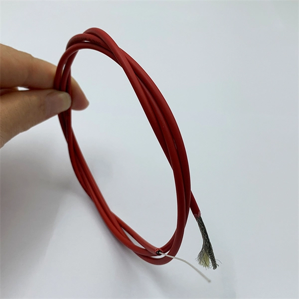
The bend radius measures how much a cable can be bent before it becomes damaged. Your cable's specifications for this will usually depend on the tensile load applied to it. These measurements will vary.
[PDF]

Our highly-skilled team of professionals specialize in the installation, termination, splicing, and testing of fiber optics technology in virtually every possible environment, including permitting services and challenging right-of-way deployments. From Complex fiber panels and management to LAN. Established in 2013, United Fiber is a leading telecommunications contractor delivering aerial and underground construction, fiber and coax splicing, turnkey engineering, and 24/7 emergency response. Headquartered in Montclair, CA, we serve Los Angeles, Orange County, the Inland Empire, and the. Parker Communications offers expert engineering capability from feasibility through HLD, LLD, and permitting. We excel in fiber network design because our FieldFirst™ engineering approach ensures engineering prints match ground-level conditions. Boots on the ground combined with multi-GIS platform. For decades, MasTec has been at the forefront of wireline infrastructure services, designing, constructing, and maintaining advanced telecommunications networks. Whether it is a new build, an infrastructure upgrade, or site maintenance, our crews handle all aspects of the project—from start to finish. Ervin Cable Construction, LLC (“ECC”) delivers quality turnkey services to multiple cable, energy, and communications companies.
[PDF]
This guide covers the essential tools and step-by-step procedures for low-loss fiber optic cable repair. Fiber optic cables are the backbone of modern networks, delivering fast and reliable data transmission. Accidental cuts, breaks, or other damage can disrupt your network and cause costly downtime. With the right tools and techniques, you can efficiently repair damaged fiber cables and restore. While a cut or damaged fiber optic cable can temporarily take your network down, it is possible to quickly fix the cable with the right tools. This wikiHow article will teach you how to splice a cut fiber optic cable back together with a fiber optic stripper and cutter and a fiber optic crimper. This complete guide covers everything from identifying causes of failure to advanced repair techniques, drawing on the latest industry standards and innovations. Begin by identifying the damage, which can be done using an Optical Time Domain. When fiber cables sustain damage, specialized repair techniques help restore connectivity and maintain data integrity. The actual steps may vary depending on the cable and/or connectors.
[PDF]
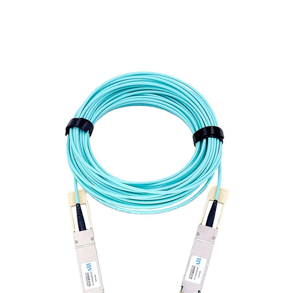
A bundle fiber optic cable refers to a type of optical fiber cable where multiple individual fibers are grouped or bundled together within the same outer sheath. Stranded fiber optic cable is a loose tube made of high-modulus plastic by adding colored optical fiber and ointment at the same time, and the optical fiber can move in the tube. Different loose tubes are twisted along the central reinforcing core to make the cable core. Instead of having individual round cables, ribbon cables have several fibers laid out side by side, typically in a flat and compact. 📦 For purchasing, use the RP Photonics Buyer's Guide for fiber bundles. It provides an expert-curated supplier directory, buyer-focused technical background information, and structured selection criteria to support professional procurement decisions. What is a Fiber Bundle? For some applications. Fiber optics, or optical fibers, are long, thin strands of carefully drawn glass about the diameter of a human hair. These strands are arranged in bundles called fiber optic cables. We rely on them to transmit light signals over long distances. This article is going to introduce fiber optic bundles, and it is configuration examples, benefits, and applications. Because the cross-section of a single optical fiber is too thin, it is not suitable for transmitting images or light, so this function is achieved by.
[PDF]

Fibre-optic Link Around the Globe (FLAG) is a 28000km (17,000miles) fibre optic mostly- submarine communications cable that connects the United Kingdom, Japan, India, and many places in between. The cable is operated by Global Cloud Xchange, a subsidiary of RCOM. These cables stretch thousands of kilometres beneath the sea, carrying the digital world across continents. New Delhi: Internet is an inseparable part of life in this modern world. Social media. These undersea cables carry almost all international data, connecting continents and countries. They're like the invisible highways of our digital world. Today, tech giants like Google, Facebook, Amazon, and Microsoft own or lease more than half of the undersea bandwidth. The world depends on digital links and the control of these cables decides how information moves between. Private telecom and technology companies own and operate nearly all submarine internet cables, which carry 99% of global internet traffic. These companies invest heavily in laying and maintaining the vast network of fiber-optic cables that connect continents and enable international data flow. The system runs from the.
[PDF]

The optical power meter is similar to the voltohmmeter in application but measures the optical resistance (losses measured in dBm or dBM) of a cable before and after installation and provides a comparative analysis of the splices. The range of the meter is adjustable. Regularly testing fiber optic cables helps minimize network downtime, lengthens the network's longevity, reduces maintenance requirements, and helps support network reconfiguration and upgrades. These factors significantly add to the fiber optic network's long-term performance, manageability, and. Several types of tests are commonly conducted to assess and maintain the health of fiber optic networks. Continuity testing verifies that the fiber is intact and that light can pass through from one end to the other without any blockages. These test procedures assess the physical and functional qualities of fiber optic cables, connectors, and the network as a whole. Key tests include: Effective fiber testing utilizes advanced tools such as Optical. One way to test a splice is to use an Optical Power Meter. As the components like fiber, connectors, splices, LED or laser sources, detectors and receivers are being developed, testing confirms their performance specifications and helps. Regular testing of fiber optic cables is not just a preventive measure; it's an investment in the longevity and efficiency of your network. By identifying potential issues early, you can enhance.
[PDF]

Fast Congo, a subsidiary of network solutions company Paratus Group in the Democratic Republic of Congo (DRC), has announced that its 620km fiber optic network link between Muanda on the west coast and the capital Kinshasa is now live, Telecoms website reported on March 21. The Democratic Republic of Congo (DRC) has launched a €66. 55 million fibre optic cable project, a significant leap towards enhancing its digital infrastructure. Funded by the African Development Bank (AfDB), the initiative boost the country's ambition to become a digital hub in Central Africa. The. The European Investment Bank (EIB) announced, Saturday, a warrant agreement with the wholesale telecommunications infrastructure provider Bandwidth and Cloud Services (BCS). Under the agreement, BCS will receive support to advance its project to build a new fiber optic backbone network in the. The Democratic Republic of Congo (DRC) government is working to improve the country's telecommunications infrastructure and expand access to telecom services nationwide. In March 2023, a 620 km fiber optic cable connecting Kinshasa and Muanda was inaugurated The SOCOF SA, Congolese Fiber Optic. The project concerns the second phase of the construction of a fibre optic backbone in the Democratic Republic of the Congo (DRC), focusing on underserved areas of the eastern part of the country. The inauguration of the.
[PDF]

Huawei's fiber to the room (FTTR) solution extends fibers to rooms and provides various gigabit Wi-Fi 6 master/slave FTTR units, all-optical components, and optical cable routing tools. This enables home users to enjoy stable gigabit Wi-Fi experience from anywhere in the home. FTTR is generally an extended FTTH (Fiber To The Home) solution. Drop optical cable terminates at ATB (Access Terminal Box). A patch cord of 1 or 2 m. Huawei will soon be selling its "FTTR" system for do-it-yourself fiber optic home cabling in Germany. Huawei FTTR: Bonding tool for fiber optic installation. A special glue. Fibeye provides FTTR(Fiber to the room) solutions, We specialize in Huawei-adapted FTTR solutions that can help you tap into new markets and grow your business. What is FTTR FTTR(Fiber-to-the-room), is an innovative solution that allows telecom operators to bring optical fibers directly into. Guess what, I spotted Huawei's transparent fibre optic offering! The best Wi-Fi is wired Last year, I wrote about Singtel's FibreEverywhere offering, which allows homeowners to install high-speed wired cabling in every room - without any drilling or trunking. Poor Wi-Fi coverage at home is a common. Watch the video to discover how to use the Huawei FTTR fiber installation kit to route transparent optical cables.
[PDF]

View 18 Communications Equipment Manufacturing company profiles below. There are 88 Telecommunications equipment suppliers in Bolivia as of November, 2025. **** Huawei Technologies. ****. Find detailed information on Communications Equipment Manufacturing companies in Bolivia, including financial statements, sales and marketing contacts, top competitors, and firmographic insights. 06% increase from 2023. 02% of all Telecommunications equipment suppliers in Bolivia are single-owner operations, while the. Market Forecast By Component (Fiber, Transceiver, Switch, Splitters, Circulators), By Technology (SONET/SDH, WDM, CWDM, DWDM, Fiber Channel), By Application (TELECOM, Data Center, Enterprise), By Data Rate (Up To 40 GBPS, Greater Than 40 Gbps To 100 Gbps, Greater Than 100 Gbps), By Vertical (BFSI. Communication Equipment NETWORKS: 1 pc. Seair is proud to have a loyal customer base from big brands. Explore verified Communication importers in Bolivia with customs shipment details, buyers list, and trade data reports for smarter import-export decisions.
[PDF]