Photovoltaic modules, or solar modules, are devices that gather energy from the sun and convert it into electrical power through the use of semiconductor-based cells. A photovoltaic module contains numerous photovoltaic cells that operate in tandem to produce electricity. A single PV device is known as a cell. An individual PV cell is usually small, typically producing about 1 or 2 watts of power. These cells are made of different. Photovoltaics (PV) is the conversion of light into electricity using semiconducting materials that exhibit the photovoltaic effect, a phenomenon studied in physics, photochemistry, and electrochemistry. Here is a description of their main features and of Enel Green Power's innovative solution. A semiconductor.
[PDF]

In this article, you will learn the step-by-step process of testing your solar panels using a multimeter. We will cover the essential tools you need, the specific measurements to take, and how to interpret the results. A $15 multimeter and 5 minutes of testing can diagnose most solar panel problems. Measure Voc (open circuit voltage) — if it reads 0V, the panel or wiring is dead. If it reads 60–80 % of rated, a bypass diode has failed. By the end of this guide, you will be equipped with the knowledge to diagnose. Learning how to test solar panel with multimeter is useful for homeowners, technicians, farmers, and anyone using solar energy systems. A digital multimeter allows you to check voltage, current, continuity, and resistance. Fluke recommends using the Fluke 117 Electrician's Multimeter or Fluke 283 FC CAT III 1500 V Digital Multimeter to test solar modules. Here's how a technician tests solar modules with a multimeter:. A multimeter is an indispensable tool for anyone working with solar panels, allowing for accurate measurements and diagnostics. It empowers users to assess the performance, identify faults, and ensure optimal energy production. Perfect for DIY solar builders, RV owners, o. more Audio tracks for some languages.
[PDF]

Passive receiver that captures an optical signal on a single fiber (1310/1490/1550nm), and demultiplexes it (WDM). The TV signal (1550nm) is converted to an RF output (54-2400MHz), while the 1310/1490nm wavelengths are destined to data signals (GPON) to distribute them through. Facilitates rapid deployment and hassle-free replacement. Contributes to wide coverage and supports multiple optical nodes, facilitating network upgrade and expansion effortlessly. Maintains stable output with minimal gain fluctuation (±0. 5dB) and low noise signature (≤5. Supports. REF. This FTTH WDM Passive Optical Receiver is engineered for high-performance fiber-to-the-home networks. It features a passive design that operates without an external power supply, simplifying installation and reducing maintenance. With integrated WDM technology, it efficiently handles 1310nm/1490nm. Passive FTTH Optical receiver, cost-effective, no need power. ■ High quality plastic case; ■ Digital signal input -10dBm, analog signal input -7dBm; ■ Without power supply and consumption; ■ SC/APC or FC/APC; ■ Output level> 64dBuV (Pin=0dB).
[PDF]

They take power from one main source and safely channel it to multiple circuits within electrical enclosures like switchgear, panelboards, and distribution boards, replacing many individual cables. Busbars are fundamental workhorses in power distribution. In electric power distribution, a busbar (also bus bar) is a metallic strip or bar, typically housed inside switchgear, panel boards, and busway enclosures for local high current power distribution, transmission, or switching substations. They are also used to connect high voltage equipment at. Current Rating: Each busbar is rated for a specific current capacity to match system requirements. This setup allows busbars to distribute large currents safely, making them vital in high-power applications. Busbars come in various forms, each suited to different applications depending on the power. Whether it's a high-voltage substation or a low-voltage battery bank, busbars ensure seamless power flow, connecting incoming and outgoing feeders effortlessly. They're not just about distributing electricity; they're about doing it faster, and safer. With modern systems demanding higher efficiency. A busbar is essentially a strip or bar of conductive metal, usually copper or aluminum. In simple terms, a busbar is a common node where multiple incoming and outgoing circuits connect. Typically made from conductive materials like copper, aluminum, or brass, busbars.
[PDF]

12KV High Voltage Epoxy Resin Through Wall Bushing for Busbar TG4-12-140x200 , made from high-quality materials with excellent craftsmanship, customisation available. Please contact us for more information. XBRELE's Epoxy Wall Bushings (also known as Through-Wall Insulators) provide reliable electrical isolation for busbars passing through grounded partitions. Featuring TG3 (KYN28) and Gas-Tight (GIS) series, molded via APG technology for zero partial discharge. Designed for high mechanical bending. Our medium voltage through-wall bushings play a critical role in electrical systems by providing reliable separation between busbars and surrounding components. We design these epoxy bushings specifically for medium voltage applications, ensuring they isolate conductors—such as quarter-inch thick. Our bushings for wall applications are specifically designed to be mounted on the wall or tank of electrical power equipment. 5 is a cast epoxy resin combined bushing busbar wall crossing device used in medium and high voltage power equipment. This equipment is usually used in substations and industrial distribution systems to achieve insulation and sealing functions when cables or busbars pass through walls. Description:Wall busing is a type of electrical equipment used to connect high-voltage cables to devices such as circuit breakers and transformers. Resistant to dirt and moisture, the epoxy.
[PDF]
In electric power distribution, a busbar (also bus bar) is a metallic strip or bar, typically housed inside switchgear, panel boards, and busway enclosures for local high current power distribution, transmission, or switching substations. They are also used to connect high voltage equipment at electrical switchyards, and low-voltage equipment in battery banks. They are generally uninsulated, and h. Design and placementThe busbar's material composition and cross-sectional size determine the maximum current it can safely carry. Busbars can have a cross-sectional area of as little as 10 square millimetres (0.016 sq in), but. • – Data transfer channel connecting parts of a computer• – Low resistance electrical conductor for high current transmission and distribution• – Modular approach t. • Elmore, Walter A. (1994). Protective Relaying Theory and Applications. Marcel Dekker.• Paschal, John (2000-10-01). Electrical Construction & Maintenanc.
[PDF]

The process involves a combination of national infrastructure, local engineering, and property-level setup. In this guide, we'll break down the fiber installation process from start to finish and explain key components such as fiber cabinets, flower pods, ducting, and ONT. Our fiber optic installation process covers everything from planning and preparation to termination and testing. But how does it work? Keep reading to find out. What Is Fiber Optic. This fiber optic installation method statement covers the termination of fiber optic cables with patch panel, network distribution cabinet NDC and door junction box but can be applicable for any kind of network installations. Roles and Responsibilities: The electrical manager shall be responsible. Setting up a fiber optic network requires careful planning and execution. This guide provides a step-by-step overview of the installation process, ensuring a smooth transition from traditional cabling systems. Introduction Installing a fiber optic network can seem daunting, but with the right. This beginner-friendly guide will walk you through the step-by-step process of fiber optic cable installation for each method, highlighting best practices, tools, and considerations. Unlike traditional copper wiring, fiber optics installation provides superior bandwidth, faster speeds, and resistance to electromagnetic interference.
[PDF]
The Patch and Splice Combo Patch Panel is designed to allow both the patching and splicing of fiber optic cable all in one unit; these particular units have fiber termination panels in the upper slide out shelf and splice trays in the lower shelf. NG4access ® Cabled Modules available in all module sizes and fiber counts up to 864 fibers NG4access ® Splice Tray Four sizes of interchangeable Propel fiber pass-through adapter packs provide the breadth of capabilities for virtually any configuration. Four sizes of interchangeable Propel fiber. Cisco is introducing a family of fiber management solutions with a debut of SMF and MMF patch panels. The panels will enable Cisco's customers to facilitate breakout connectivity agnostic of the data rate. The Cisco® solution of panel and cable assemblies offers versatile solution for any breakout. Our fiber patch panel offers options for flexible cable management and seamless integration with various cassettes and fiber optic accessories. Allowing full front access for network. Foss FP-series front patch panels are made with the highest accuracy for precise fitting. All panels are tested according to both our own quality measures and international standards before they are sent to customers. Similarly, the ABS High Density Shelves bring a new level of access, convenience, and security to its Fiber Splice Shelf, enabling quick and easy fiber splicing and connectivity for rack mount applications.
[PDF]

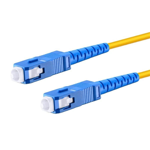
In this video, Joe would display how to connect SC fiber optical connector in 2 minutes. Related product:. Step 4 i s to affix the fiber to the connector. The fiber should be inserted into the connector until it is flush with the ferrule end. Step 5: Let the epoxy cure. These connectors ensure high-quality signal transmission, which is essential for reliable internet and communication services. SC APC connectors offer superior optical. There are many types of fiber optic connectors, including SC, LC, FC, ST, D4, MU, MT/MPO, etc. These connectors can be divided into single-mode and multi-mode fiber optic connectors according to their structure and purpose. To learn more about the types of fiber optic connectors, click here: Types. The global SC fiber optic connector market is valued at approximately 903 million USD in 2025 and is projected to grow steadily, which reflects its continuing role as a standard interface in fiber infrastructure, including plant backbones and industrial automation links, according to SC connector. SC fiber connectors, or Subscriber Connectors, are widely used in telecom and networking for their strong performance and easy handling. They're known for a secure push-pull connection that's quick to insert and remove.
[PDF]

How to Install a Fibre Connector into a Patch Panel (Easy fibre optic connector installation) How to Install a Fibre Connector into a Fibre Optic Patch Panel. How do you install fibre optic connectors?. Connecting a fiber patch panel to a switch is a critical step in setting up a fiber optic network. There are different types of connectors. In today's high-performance networks, fiber optic patch cables are the lifelines that ensure smooth data flow across switches, servers, and routers. Even the most advanced optical transceivers can only perform at their peak when paired with properly installed, clean, and precisely managed fiber. Choose an SFP module based on the fiber optic cabling that will be connected to the network switches. SFP transceiver modules almost always require two fiber optic cable strands. A Fiber Patch cord connects two devices. You plug it into a switch, router, or patch panel. It's ready to use out of the box. A pigtail is for splicing. You fuse it to a. With a railroad switch (patch panel), the train (data) can travel from A to B, C and even more destinations, otherwise it can only go from A to B, or C to D. This article, What Is a Patch Panel Used for?, has explained it thoroughly.
[PDF]
Voltage level: Industrial facilities often use multiple voltage levels (such as 1kV, 10kV, 400V), and it is necessary to ensure that the cable distribution box layout separates different voltage systems to avoid interference. A distribution box is the heart of any electrical system. It takes the incoming power and safely distributes it to different circuits throughout your building. Whether in a home or an industrial facility, this box keeps your electrical setup organized, functional, and efficient. However, the key to. Design requirements for low voltage distribution boxes cover NEC, IEC, and safety standards to ensure reliable, compliant electrical installations. You must make safety your top priority when working with low voltage distribution boxes. Protection requirement: According to the fault risk (such as short. For Branch Circuits (the conductors spanning from the final overcurrent device or breaker to the actual outlet, light fixture, or equipment), NEC Informational Note No. 4 recommends a maximum voltage drop of 3%. This ensures that the device at the end of the line receives at least 97% of the panel. For distribution boxes that handle only lighting circuits or small power loads, if the incoming wire size is less than 10 square millimeters and the number of circuit switches is fewer than 20, the width of the box should be calculated by summing the width of the switches and adding an additional.
[PDF]

Learn how to seal electrical enclosures effectively to protect equipment from moisture, dust, and harsh environments. Step-by-step guide and expert tips. An electrical box sealant is a specialized material used to create an air-tight and water-resistant barrier around electrical enclosures and their penetrations. This practice is a fundamental part of maintaining a structure's envelope. It prevents the uncontrolled movement of air, moisture, and. To put it simply, the sealing ring is extremely important for the waterproof distribution box, as it directly determines whether the inside of the enclosure can remain dry at all times. Common sealing designs on the market typically use one-piece molded polyurethane foam or EPDM rubber strips. Whether in a factory. Selecting the appropriate materials is key to effectively air-sealing electrical boxes. Various products are available, each suited for different scenarios. Foams are commonly used for sealing gaps around electrical boxes. For small gaps, we recommend a high-quality insulating foam like Gaps &. How can we improve? Choose from our selection of electrical enclosure seals, including gasket tape for enclosures, washdown hole plugs, and more. Polylok offers the only catch basin and distribution box seal on the market that accepts multiple size pipes. After choosing your inlet/outlet holes and cutting them out, the seal is easy to install.
[PDF]

Perform a dielectric strength test to check the insulation properties of the busbars under high voltage conditions. The Partial Discharge test is crucial for determining long-term part. A busbar protection must be capable of clearing all phase-to-earth faults, and in the case where they can occur, phase-to-phase faults. Policy regarding fault clearance times required from busbar protection varies from utility to utility. Due to the fact that the short-circuit levels of bus bars. Early detection of cracks is crucial for preventing. Check the mechanical. The voltage of the faulted phase decreases (in case of incomplete grounding) or drops to zero (in case of solid grounding). In stable grounding, the. Busbar Differential Protection Definition: Busbar differential protection is a scheme that quickly isolates faults by comparing currents entering and leaving the busbar using Kirchoff's current law. Current Differential Protection: This protection method connects CT secondaries in parallel and. That's based on air insulated buswork well above your head and a reasonable set of remote zone 2 times. I agree with you as chances of surviving a bus fault is practically non existent at 110/220kV regardless if its cleared in ~100ms via busbar prot scheme or via remote end in zone 2 times of.
[PDF]

