
Run a ground wire from your metal patch panel rack to the grounding bar, use grounding lugs on the rack. Probably not necessary, but use Noalox between the lug and the rack. Remove paint if you want to go all in. Install and ground coax grounding blocks for your antenna. A Cat6 shielded patch panel is a modular component that connects and organizes multiple Ethernet cables in a central location. Unlike unshielded panels, shielded patch panels feature a conductive metal body and a grounding terminal to block EMI and maintain network integrity. GYA's shielded patch. A patch panel is a hardware device used to organize and manage network cable connections, helping to keep network wiring neat and efficient. Based on the shielding type, Cat6 copper patch panels are categorized into two types: shielded and unshielded. The rack itself is then bonded to the Secondary Busbar (SBB) of the telecommunications room. This. Correct STP grounding turns shielding into real EMI protection. This guide shows how to maintain drain‑wire continuity, bond safely at the equipment side, avoid ground loops, and validate results with simple tests. Cabling is cat5e UTP for data and phone. Coax is RG6 with 2 seperate runs, one for commercial tv provider, other for an attic mounted antenna that I'd like to eventually move to the roof. Is there a requirement (USA NEC) to.
[PDF]

Our guide delivers actionable, step-by-step best practices for rack layout, cable management, and patch panel installation. Following these steps helps you build a clean and efficient structured cabling system that simplifies maintenance and maximizes network performance. Patch panels are one of the best ways to manage an expansive local area network (LAN) by providing quick and easy access to the ports and connections that connect them altogether. Before a single cable is. H. Use cabinet screws to fix the network patch panel to the network cabinet. Note the wiring sequence on the patch panel when wiring, as T568A and T568B have different sequences. Different brands of patch panels may also have different wiring sequences, so always pay attention to the sequence. A patch panel is a board that houses multiple network ports. It acts as a bridge between incoming and outgoing Ethernet cables. Instead of plugging and unplugging devices directly from network switches, you connect them to the patch. Patch panels are a crucial component in any network infrastructure, providing a centralized location for managing cables and connections. By using patch panels, network administrators can simplify cable management, improve network scalability, and reduce downtime. This innovative tool combines precision with automation, ensuring accurate network documentation for IT professionals and network administrators.
[PDF]

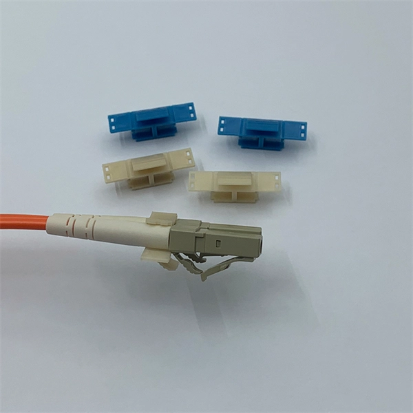
Just count the number wire leads coming from the connector and scroll to the section with that number. Executive Summary: A fiber optic pigtail is one of the most commonly specified yet least understood components in structured cabling. Get the wrong connector type, the wrong polish, or skip proper fusion splicing technique—and you're looking at elevated signal loss, increased back reflection, and a. Terminal Release Tools RTTP #s: NUD900-001, NUD900-002, NUD900-003 and NUD105-R025E Flex Probe Kit are available through RTTP. 2ND GENERATION - EXPANDED TO INCLUDE 8 AWG APPLICATIONS! Ford has identified through testing and engineering analysis, the optimal repair procedure for solderless wire. It includes an identification guide with images of various connectors and kits, highlighting their use in vehicle electrical repairs. The document details specific toolkits such as the Ford Flex Probe Kit and the Wire Splice Tool Kit, designed for repairing electrical wiring harnesses. Match the connector in the picture. They contain 5 uninsulated butt splices, 5 pieces of dual wall adhesive-lined heat shrinkable tubing, and the new instruction sheet detailing the approved wire splice procedure as defined by Ford Motor Company. Expanded wire gauge applications for these splices can be found in Technical Service.
[PDF]
The applicable subheading for the fiber optic panel/chassis and fiber optic patch tray, will be 9403. 8040, Harmonized Tariff Schedule of the United States (HTSUS), which provides for “Other furniture and parts thereof: Parts: Other: Other; Of metal. ” The rate of duty will be free. Item 1, part number LCXE-M1RU-BLK, is described as a fiber optic chassis with the capabilities of holding twelve fiber optic cables. The panel is produced from cold rolled. The merchandise is fiber optic patch panels that provide a consolidated point of demarcation for optical terminations, connections and cross connections within a passive, fiber optic network. They are designed to be mounted onto a wall or rack. All fiber optic patch panels will consist of the. Find verified buyers and sellers of Fiber Optic Patch Panel in 180+ countries along with their valid phone numbers and email ids. The top 3 Buyer countries for HS Code 851770 are “ PHILIPPINES ”, “ INDIA ”, “ PAKISTAN ”,. com if you have any questions or special project needs. The panel is produced from cold rolled. In the United States, customs duties imposed on imports from Asian countries have increased costs for Internet service providers and telecommunications companies, in many cases delaying infrastructure expansion and maintenance projects. In Latin America, several countries have adopted tariff.
[PDF]

Explore 39 top manufacturers and suppliers of Fiber Optic Patch Cords in our comprehensive photonics buyers' guide. Manufacturer of fiber optics and related instrumentation, components, and assemblies for spectroscopic and laser delivery applications. Fiberopticpatchcords are also offered. Packaging, prototyping, engineering drawing, labelling, and kitting are offered as secondary services. Serves electronics. In the United States, there are many professional network patch cord manufacturers that can manufacture and supply high-quality Category 5, Category 6, and Category 6A RJ45 patch cables. But it's a bit difficult to find the best one with the most competitive price. To help you find the best. This section provides an overview for fiber patch cable as well as their applications and principles. CBO GmbH. fiber optic patch cord manufacturer should be selected by connector type, single mode or multimode fiber, polish type, cable diameter, jacket material, length, insertion loss requirement, labeling, packaging, and quantity. Products include fiber optic assemblies for. This report studies the Optical Fiber Patch Cord market, also known as fiber optic patch cable or fiber jumper, it is an Optical Fiber Patch Cord is a fiber optic cable capped at either end with connectors that allow it to be rapidly and conveniently connected to CATV, an optical switch or other.
[PDF]

As a critical component in high-speed networks, fiber optic patch cords require micron-level precision. This guide unveils the complete production workflow compliant with **IEC 61754** and **Telcordia GR-326-CORE** standards, featuring proprietary quality control. If you've ever troubleshot a fiber optic network only to find that a microscopic dust particle caused the entire system failure, you understand why IPC-8497-1 exists. This standard represents the industry's collective wisdom on how to properly clean and assess contamination in optical assemblies. For harsh environments or other data center and IT networking applications where there is a greater risk of damage to your fiber optic network, armored fiber optic cables deliver the protection you require. Built with a steel-armored layer that provides extra crush and rodent resistance, these. Welcome to be our agent! Fiber optic patch cords, also known as fiber jumpers, are essential components in high-speed data transmission networks. Their performance directly impacts signal quality, insertion loss (IL), and return loss (RL). At ZION Communication, we design and manufacture a full range of fiber patch cords for: This guide will help you quickly understand the main types of. Ensuring the performance and reliability of fiber optic patch cords is fundamental to optical network integrity. 6-Step Manufacturing.
[PDF]
Here's a step-by-step guide to help you properly arrange fiber optic patch panels in a data center environment. Before installation, assess your network's current and future needs:. Effectively arranging optical fiber optic patch cords in a cabinet is a critical aspect of maintaining a streamlined and organized network infrastructure. Proper arrangement not only enhances the overall aesthetics of the cabinet but also plays a crucial role in preventing signal interference and. As networks move to higher speeds and higher density, choosing the right fiber optic patch cords becomes critical to the reliability of your system. At ZION Communication, we design and manufacture a full range of fiber patch cords for: This guide will help you quickly understand the main types of. You need fiber patch cord installation and maintenance for a strong network. If you do not handle them well, connectors can get misaligned. Rough handling can also cause problems. Fiber optic patch cords, also known as fiber optic patch cables or fiber jumpers, are indispensable components in modern optical networks. They act as the critical link for interconnecting devices like optical switches, servers, and distribution frames. Understanding the various technical. You need fiber optic cables. But the options are overwhelming. One customer ordered 50 LC-SC patch cords. They were all the wrong polish type. The network failed during testing. This happens more than you think.
[PDF]

An €80 million loan (equal to about XOF 52. 5 billion) from IFC and other investors will enable Orange Mali to install 300 new 4G towers and expand its fiber network to reach an estimated 300,000 households and smaller businesses in Mali. Mali's government has reportedly contracted China International Telecommunication Construction Corporate to extend the country's national fibre-optic network. According to Agence Ecofin, the work will be carried out as part of a USD117. To expand access to quality and affordable connectivity and. Bamako, Mali, November 17, 2025 — To expand access to quality and affordable connectivity and digital financial services in Mali, especially in rural areas, IFC today announced a partnership with Orange Mali SA to support the company to upgrade its infrastructure, expand broadband coverage, and. The Malian government seeks to strengthen the national telecom infrastructure as part of its digital transformation ambitions. The aim is to gradually include the 65% of the population who, according to DataReportal data, still lack access to the Internet. With a total cost of 117. 3 million USD, the project was approved by the Council of Ministers on Wednesday January 3.
[PDF]

In this guide, we'll walk you through exactly how to splice fiber without a fusion splicer, covering the tools you need, the step-by-step process, performance specs, and common mistakes to avoid. By the end, you'll be equipped to make clean, low-loss connections in any. In this guide, we cover the basics of fiber optic splicing, how to perform splicing using two different methods, and finally some best practices to perform good fiber splicing. What is Fiber Optic Splicing and Why is it Needed? – #1. Use and Maintain Your. Optical fiber fast connectors, also known as cold connectors, are becoming increasingly popular due to their ease of use and quick installation. Unlike traditional fiber connectors that require epoxy and polishing, fast connectors use a mechanical splice to join the fibers. What is a. Three methods for connecting two fiber optic cables: fusion splicing, mechanical coupler, and splicing. Whether repairing a broken cable or extending a fiber run, fiber optic splicing ensures light signals travel. Fiber optic splicing is the art and science of joining two separate optical fibers to create a continuous light path. This process requires precision, patience, and a deep understanding of the delicate nature of optical fibers. Before any splicing can occur, whether it's mechanical or fusion.
[PDF]

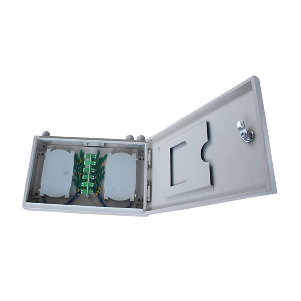
A Fiber optic cap type splice box is a protective enclosure designed to house and organize fiber optic splices. It typically features a dome or cap-style closure that provides a sealed environment for fiber joints, protecting them from external conditions. As fiber optic networks continue to expand across urban, rural, and industrial environments, the reliability of connection points becomes. The cap-type splice box is mainly designed for laying optical cables in overhead and tunnels. It does not meet the waterproof requirements of the regulations when used in direct-buried lines, but the moisture-proof effect in lines is better. According to regulations, the open type and other three. The types of optical cable splice boxes can be divided into cap-type optical cable joint boxes and horizontal optical cable joint boxes according to the shape and structure. According to. Grandway's fiber optic closure provides a high density wall mounted or pole mounted solution for next generation networks, which aims to provide and manage fiber splitters in a limited space. It is designed for FTTH (Fiber to the Home) or FTTB (Fiber to the Building) with protective housing for all. Briefly explain how fiber splice closures are critical for network protection and performance optimization. Introduce that choosing between dome (cap-style) and horizontal (in-line) closures depends on specific project requirements. Understanding Fiber Splice Closure Types 1.
[PDF]

And fixed the frame on the front door position with 4 M5*8 self-tapping screws. 2, Use 16 M8*12 inner hex round screws and M8 flange nut for fixing the top & bottom panels into two side frames. 4, Insert back panel. Follow the instructions in this section to remove and install the side panels. Insert the key that comes with the rack cabinet into the key hole on the side panel, and turn it clockwise to unlock. If an IT cabinet is not equipped with side panels and placed in the end position, side panels need to be installed to ensure that the outer side of an end cabinet has side panels. Mark the mounting hole positions for the end cabinet based on the mounting holes in the cabinet side panel, and install. Complete Assembly Procesure for 9U Wall Mounted Network Cabinet (Single Section) How to assemble a wall-mounted network cabinet? 1, Insert top and bottom panel into the side frames. more How to assemble a wall-mounted. Installing and setting up a network cabinet system correctly is essential for maintaining an efficient and organized network infrastructure. In this comprehensive guide, we will walk you through the step-by-step process to ensure a successful installation and setup of your network cabinet system. Page 3 M3. 5 Attach Back Panel (H) to the rear of the cabinet frame,using M3. Click Side Panels (E) into place. To install the Tempered Glass Door (G), locate the side with two pins. Insert the fixed pin into door hinge hole. Pre – installation.
[PDF]

In this guide, we'll walk you through the entire process of preparing fiber optic cable for splicing and termination to fiber connectors. We'll explore the necessary tools, safety precautions, and step-by-step procedures for cable connectors, mechanical and fusion. At the heart of any robust fiber optic network lies a crucial process: Preparing a fiber cable for termination of a connector or splice. Two types of splices are used in fiber optic cabling one is Mechanical the other is Fusion. Whether you're installing a new network, expanding an existing one, or. Splicing fiber optic cable is an extremely important phase for making dependable, high-speed communication infrastructures. Regardless of the type of fiber network you're deploying, be it for telecom, enterprise data centers, or smart city infrastructure, fusion splicing provides the benefits of. Think of a fiber optic cable splice as the seamless stitching that keeps data flowing through the delicate threads of a network—like a master tailor joining fabric with precision. This article explains when. We terminate fiber optic cable two ways - with connectors that can mate two fibers to create a temporary joint and/or connect the fiber to a piece of network gear or with splices which create a permanent joint between the two fibers. These terminations must be of the right style, installed in a. So in essence, fiber optic splicing is a process used to join two separate fiber optic cables together.
[PDF]
Fiber optic patch cables are ideal for supporting high speed telecommunication network fiber applications. They are manufactured and tested in compliance with TIA 604 (FOCIS), IEC 61754 and YD/T industry s.
[PDF]
