Picking up the best router for fiber internet isn't just about going to the market and choosing one of the best wireless routers. Instead, you need to carefully look at its specs, performance, and the type of securit.
[PDF]

When selecting a 48 core fiber optic cable, prioritize single-mode over multimode for long-distance, high-bandwidth applications such as telecom backbones or data center interconnects. Look for cables with loose tube construction, robust armor (if outdoor use), low attenuation (<0. 4 dB/km at 1310. • Fiber optic cables are often custom cut to match required lengths for each cable run, or you can order a reel matching your total length and cut segments yourself. It's advisable to include a safety buffer when ordering, with an additional 10% being common practice, despite careful measurement of. Fast data transmission, thinner, lighter cables and long signal range are just a few of the benefits that make fiber optic cable a solid choice for corporate data networking and telecommunications. Fiber cores are the heart of fiber optic cables, transmitting light signals that carry data. Made from either high-quality. But when it comes to selecting the right fiber optic cable for your environment, there are several key considerations and a variety of attributes to choose from, ranging from type of fiber and strand count to construction and application. Unlike copper wires, which are limited by lower data transmission speeds, shorter transmission distances, and higher susceptibility to electromagnetic interference, fiber optic cables offer unparalleled performance and can.
[PDF]
The QSFP28 optical transceiver module is designed for use in 100GBASE Ethernet throughput up to 100km over single mode fiber (SMF) using a wavelength of 1310nm via duplex LC connectors. The 100 Gigabit Ethernet signal is carried over four wavelengths multiplexing and demultiplexing of the four. 100G ZR4+ optical module provides up to 103. 12Gbps data rate using QSFP28 footprint at the wavelengths of LWDM, which is designed with digital diagnostic monitoring. All Rights Reserved. GigOptics is a leading supplier of Optical Transceivers in the USA. We offer a wide range of products at great prices with fantastic service (SFP, SFP+, SFP28, QSFP+, QSFP28, XFP, etc. Various Switch Tests: Each module is quality tested for compatibility in the multi-brand switches. Comprehensive Testing: Each. The 100GBASE-ZR4+ QSFP28 delivers 100 km reach over single-mode fiber without external amplification. With a 34 dB link budget (FEC enabled) and integrated SOA receiver, this is the longest-reach 100G option in the QSFP28 form factor. 4 LAN WDM lanes at 103.
[PDF]

This document provides a comprehensive framework for the classification, characteristics, and operational parameters of Multi-Degree Reconfigurable Optical Add/Drop Multiplexers (MD-ROADMs), including two-degree ROADMs. com 2 Telecom service providers are adapting their optical backbone networks to meet the demands of cloud networking and relentless video- and mobile-data traffic growth. Combined with a move to ultrahigh-capacity. What is ROADM? ROADM (Reconfigurable Optical Add-Drop Multiplexer) is a key component of optical transport networks (OTN / DWDM systems). It enables adding (Add), dropping (Drop), or passing (Pass) optical channels remotely and flexibly without converting optical signals to electrical signals. PacketLight's PL-1000RO/GRO 4/8/32-degree CDC-F ROADM offers functionality based on advanced next generation wavelength-selective switch (WSS) technology. It allows for flexible and dynamic routing of optical signals by adding (inserting), dropping (extracting), and passing through (routing) specific. Optical Add-Drop Multiplexers (OADMs) are essential components in Wavelength Division Multiplexing (WDM) networks, enabling the selective addition and removal of specific wavelengths within an optical fiber to enhance bandwidth efficiency. With ongoing advancements, OADMs have evolved from FOADMs.
[PDF]

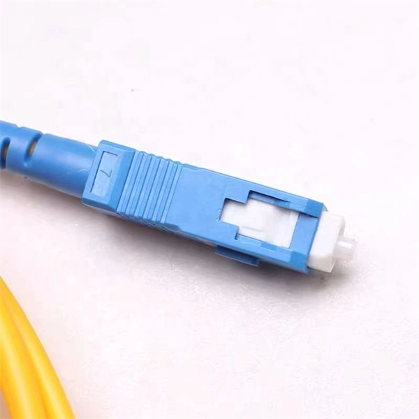
They directly point to the module type. Additionally, observing the color of the optical module's pull tab is a straightforward way to check it. Multimode: Pull tabs are typically black. Another very direct method is checking the. How to distinguish whether an optical fiber module is single-mode or multi-mode? Optical modules are core photoelectric conversion components in fiber-optic communication, data centers, enterprise networks, and telecom transmission systems. Correctly distinguishing single-mode and multi-mode. Understanding whether your SFP module is single-mode or multimode is crucial in network design. The choice impacts the transmission distance, data rate, and cost of your setup. Typically, single mode SFP modules are labeled as "SM" or "single mode," while multimode modules may be labeled as "MM" or "multimode. ". To determine whether the SFP module in your hand is single-mode or multi-mode, the most straightforward method is to check the color of the pull ring, for example, blue pull rings and red pull rings are single mode, and black pull rings are multimode. Multimode (MMF) SFP modules involves a cross-referencing protocol of physical bail colors, EEPROM telemetry, and wavelength specifications. Precise verification prevents "Ghost Links" and Mode Field Diameter (MFD) mismatches that degrade 800G AI fabric performance.
[PDF]

These installation instructions provide overview and specification information for small form-factor pluggable (SFP/ SFP+/SFP28) modules, as well as instructions for installing and removing the modules. SFP (Small Form-factor Pluggable) transceivers are essential components in modern fiber optic networks, enabling network devices such as switches, routers, and servers to transmit and receive data over optical fiber. By converting electrical signals into optical signals—and vice versa—SFP. Gigabit single-mode fiber optic module Common parameters of optical modules 1. Center wavelength 1) 850nm (MM, multi-mode, low cost, but short transmission distance, usually only 500M); 2) 1310nm (SM, single mode, large loss during transmission, small dispersion, generally used for transmission. As a leading provider of fiber optic solutions, Weunion offers a wide range of SFP-compatible products, including optical transceivers, DAC/AOC cables, LC patch cords, and MPO/MTP assemblies. While they may appear to be simple plug-in transceivers, SFP modules are precision-engineered devices that directly influence network. o In optical modules, "core" refers to the light-transmitting channel in the fiber. A 1-core module uses a single fiber core for data transmission, while a 2-core module uses two cores. o Think of a highway. A 1-core fiber is like a single-lane road—only one car (or data signal) can travel at a.
[PDF]
Voltage Limits: Set upper/lower bounds to match your grid requirements. MPPT Tracking: Adjust Maximum Power Point Tracking for varying sunlight conditions. Frequency Response: Ensure synchronization with grid frequency (50Hz or 60Hz). This paper presents a concise discussion and an investigation of the most literature-reported methods for modifying the lumped-circuit parameters of the single-diode model (SDM) of a photovoltaic (PV) module, to suit the prevailing climatic conditions of irradiance and temperature. These. This page gives access to several tools for the determination of all secondary parameters of the PV module model. PVsyst always proposes default values which may be recovered by clicking the " Default " checkboxes. The main goal is to determine the optimal parameter. This guide will walk you through practical steps to optimize your inverter settings, whether you're a solar technician, project manager, or a business owner looking to maximize ROI. Think of your inverter as a translator between solar panels and the grid. If it's not “speaking the right language,”.
[PDF]

Scattering accounts for the greatest amount of attenuation in a fiber cable, between 95 and 97 percent. Light traveling through the fiber interacts with the densities as shown in the light and is then partially scattered in all directions. Fiber optic cables have many advantages, but one of the downsides just like with copper cable, is that it can experience what is called attenuation. Attenuation refers to the loss of light as it travels down the fiber. This can be due to a variety of factors: scattering and absorption, intrinsic. This attenuation is inevitable, so the smaller the attenuation value, the longer the transmission distance of the same optical power. The better the quality of this fiber patch cable. It indicates the amount of signal reflected back. At TREND Networks, we are frequently asked how much loss is allowed when conducting testing on fiber optic cabling. Unfortunately, it is not a simple answer and depends on several factors. So how do you determine acceptable loss? When testing fiber optic cabling, determining acceptable loss is. Understanding fiber loss is vital in maintaining a reliable, efficient network. Understanding it is crucial for anyone involved in data centers, telecommunications, or enterprise networking. Here are the details and instructions about each field and how they contribute to the calculation: 1. Attenuation Coefficient (dB/km): This value represents the inherent signal loss per kilometer of.
[PDF]

This guide covers the critical steps, from selecting the right electrical cable tray and performing accurate cable fill calculations to managing a safe cable pull through and ensuring all bonding and grounding requirements are met. The purpose of this article is to define the sequence and methodology for the installation of electrical cable trays, cable trunking, cable raceways and boxes, junction and pull boxes. The method gives details of how the work will be carried out and what health and safety issues and controls that. The Cable Ladder & Tray Components – Assembly Guide presents a comprehensive visual walkthrough of the assembly and installation process for cable ladder and tray systems. The images meticulously detail each component involved, including ladder sections, cross-members, splices, and tray segments. Ladder style cable tray is a device used to support and protect wires and cables, commonly used in buildings, industries, and commercial places. The following are the installation steps for ladder style cable trays: 1. Preparation of tools and materials: The tools and materials required for the. Whether you're building a commercial setup or upgrading an industrial plant, proper cable tray installation ensures neat wiring, safe access, and easy maintenance. This guide breaks down the process step by step. Cable ladder systems and cable tray systems shall be manufactured in accordance with BS EN 61537, channel support.
[PDF]

In this video, we'll show you how to connect an energy meter to a distribution board (DB) safely and efficiently. A residential electric meter box wiring diagram illustrates the connection between the utility service drop and the main breaker panel. It shows the hot wire entering the meter lugs, the neutral wire connecting to the neutral bus bar, and the essential ground wire linkage to ensure system safety. energy meter connection with distribution box How to Connect an Energy Meter to Your Distribution Box Easily Steps to Properly Connect Your Energy Meter to a Distribution Box. This prevents arc faults and ensures safety when modifying or inspecting current paths. Inside the service housing, line conductors from the utility feed typically enter through the. The wiring that links the utility company's service point to a home's electrical distribution system is the main service connection. This “meter to panel” wiring establishes the pathway for all incoming electrical power from the grid to the home. Whether you're an electrician or a DIY enthusiast, this guide will help you understand the basics of home electrical distribution. What is Distribution Board? Distribution board.
[PDF]

Connect the red wire to the copper wire with the red color bar of the optical/electrical composite cable, and connect the black wire to the other copper wire of the optical/electrical composite cable. Then press and secure the crimp tube. Ensure that no copper. The composite fiber optic cable is a type of cable that combines both fiber optic and copper conductors within a single cable sheath. This hybrid construction allows for the simultaneous transmission of data using fiber optics and electrical power or additional data using copper conductors. How to Use the Composite Fiber Optic Cable? To begin, you need to gather all the accessories and equipment required: 1. Waterproof Industrial-Grade Fiber PoE Media Converter Compatible with the IEEE802. Cut the cable along the center and pull one copper cable on the left and right sides to the position shown in the figure to expose the optical fiber. Whether you're a seasoned technician or a beginner, this guide has something for everyone. more In this video, we'll walk you. In a previous blog, we covered what to do when you need to connect a device that is located beyond the 100-meter distance requirement and described four ways to address the problem—a new TR, the use of an extender device, extended-reach copper cable and fiber. This article will guide you through the necessary tools, materials, and methods on how to connect fiber optic cables effectively.
[PDF]
The formula for calculating electrical box size is: [ BS = (N times D) + A ] Where: ( BS ) is the box size in cubic inches. ( N ) is the total number of conductors. Article Summary: Calculating the correct junction box size per the NEC 2023 involves a process known as a “box fill calculation,” primarily governed by NEC Article 314. This count includes each conductor. Get the exact dimensions you need for a production quote. How It Works: Enter Your Product Details: Input your item's length, width, and height. Set Your Quantity: Tell us how many items you want to pack in each carton. ( A ) is the volume allowance for any device or fitting. How do I calculate box fill fast? This electrical box fill calculator (or in short, box fill calculator) will help you determine the total box fill volumes you will need to meet so that each of your electrical utility boxes will pass the National Electrical Code®. In this calculator, you will. Determine the proper junction box size for your electrical installation by calculating volume requirements, fill percentages, and ensuring compliance with electrical codes and safety standards.
[PDF]
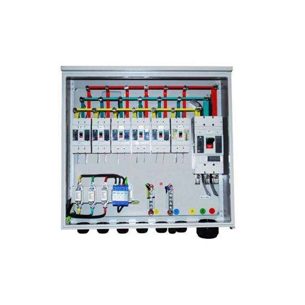
Connect the input and output wires to the corresponding terminals of the distribution box. Then press the wire onto the terminal with a wire stripper, or tighten the wire with screws. This step is very crucial and can not bear any faults!. In this video, we'll walk you through the process of wiring a home distribution box with a detailed connection diagram. more Welcome to our channel! In this video. This guide provides step-by-step instructions for connecting a distribution box and highlights key factors to consider during installation. What Is a Distribution Box? A distribution box, also known as an electrical distribution board, is a critical component in electrical systems. It serves as a central hub for distributing electricity throughout a building, ensuring that power is delivered safely and efficiently to all the required locations. It is usually equipped with circuit breakers, fuses, terminal connectors, and other components.
[PDF]

