
This guide will walk you through the most common fiber connector types, explaining their characteristics, advantages, and typical use cases. An optical fiber connector is a device used to link optical fibers, facilitating the efficient transmission of light signals. An optical fiber connector enables quicker connection and disconnection than splicing. Whether you're planning an FTTH deployment, upgrading a data center, or working in telecom infrastructure, this guide will help you make informed decisions. This guide provides a fully updated and industry-ready overview of LC fiber optics, explaining the origin and design of LC connectors, their key features, and the complete ecosystem of LC-based products used in modern networking. It covers LC connectors, LC patch cables, uniboot designs, armored. Fiber connector types LC, SC, FC, ST, MTP, and MPO are widely used in past and present. What are the differences between them? Who is the most popular one? Find the answer in the article. What is a Fiber Connector? The optical fiber connector is a kind of detachable passive optical component used. The answer often lies in tiny but mighty components called LC connectors. There have been many types of connectors developed for fiber cable. Single mode networks have used FC or SC.
[PDF]

In this video, we'll walk you through the process of wiring a home distribution box with a detailed connection diagram. In this article, we will delve into the details of an electrical sub panel diagram, discussing the various components, their functions, and the proper wiring techniques. Whether you are a homeowner tackling a DIY electrical project or an electrician looking to expand your knowledge, this guide will. A 30-amp sub panel functions as a secondary electrical distribution point, receiving power from the main service panel to serve a localized area. This small panel is commonly used to provide lighting and receptacle power to detached structures like a garage, a workshop, or a small shed. more Welcome to our channel! In this video. Load Calculation: Perform a load calculation to determine the total electrical load of the building. This involves calculating the power requirements of each individual device or system and adding them together to get the total load. It is important to ensure that the wiring and subpanel can handle. An electrical panel box, also known as a breaker box or a distribution board, is a crucial component of any electrical system. It serves as a central hub for distributing electricity throughout a building, ensuring that power is delivered safely and efficiently to all the required locations. ) is a cabinet or cutout box which contains on controlling and protective devices (such as circuit breakers, fuses, switches etc.
[PDF]

Fiber optic network diagrams represent the architecture and connectivity of fiber optic systems, and their design philosophy integrates technical, functional, and conceptual aspects. The diagrams abstract complex details of fiber optic systems to make them. Fiber optic network design refers to the specialized processes leading to a successful installation and operation of a fiber optic network. It includes first determining the type of communication system (s) which will be carried over the network, the geographic layout (premises, campus, outside. A fiber optics network diagram illustrates how high-speed data travels from an internet service provider to end users. These diagrams help engineers plan infrastructure for residential and commercial buildings. What is fibre network mapping? Fibre network mapping is a critical process in the planning, deployment, and management of fibre optic networks. I'm needing symbols for common fiber optic components, cables, connectors, backbone ports, etc. Can anyone help me out? Some examples of a diagram would also help. 10-27-2018 01:41 AM Do you know if there's some symbol standard. Definition: Fiber optic cable is also called the “ Optical Fiber Cable “, and it is simply Ethernet networking cable that contains the multiple optic fibers, and they allow to transmit data with massive volume. Main goal of designing the optical fiber cable is to offer ultra performance data.
[PDF]

This AutoCAD DWG file includes a complete Single Line Diagram (SLD) of a Distribution Board, showing circuit breakers, wiring connections, and load distribution for lighting, power, and mechanical systems. An electrical panel box, also known as a breaker box or a distribution board, is a crucial component of any electrical system. It serves as a central hub for distributing electricity throughout a building, ensuring that power is delivered safely and efficiently to all the required locations. Whether you're an electrician or a DIY enthusiast, this guide will help you understand the basics of home electrical distribution. What is Distribution Board? Distribution board. Welcome to our channel @Electricalgenius In this video, we'll take you through a detailed step-by-step guide on wiring a home distribution DB (Distribution Board) box. A distribution board (also known as a service panel or breaker box) is a centralized collection of circuit breakers, fuses, and/or relays used to control and protect the wiring in a home. The diagram. To understand how a breaker box works, it is helpful to have a wiring diagram that shows the connections between the various components. At the heart of a breaker box is the main breaker, which controls the flow of electricity from the utility into the building. This breaker is connected to a.
[PDF]

Fiber optic network diagrams represent the architecture and connectivity of fiber optic systems, and their design philosophy integrates technical, functional, and conceptual aspects. The diagrams abstract complex details of fiber optic systems to make them understandable for. Fiber optic network design refers to the specialized processes leading to a successful installation and operation of a fiber optic network. It includes first determining the type of communication system (s) which will be carried over the network, the geographic layout (premises, campus, outside. A fiber optics network diagram illustrates how high-speed data travels from an internet service provider to end users. These diagrams help engineers plan infrastructure for residential and commercial buildings. It includes detailed mapping of backbone, distribution, and drop connections for FTTH, FTTP, FTTx, and enterprise networks. Planning and design is a process that includes many decisions, involving first defining the communication protocols to be used on the network and defining geographical layout. It also involves selecting transmission equipment.
[PDF]

Welcome to our channel! In this video, we'll walk you through the process of wiring a home distribution box with a detailed connection diagram. What is Distribution Board? Distribution board. These smaller breaker panels, also known as sub-distribution boards, are commonly used to provide power to secondary circuits within a building. Understanding the components and wiring configuration of an electrical sub panel is essential for safe and efficient electrical installations. In this. Primary distribution systems consist of feeders that deliver power from distribution substations to distribution transformers. A feeder usually begins with a feeder breaker at the distribution substation. Many feeders leave substation in a concrete ducts and are routed to a nearby pole. This breaker must be compatible with both your main system and the additional connections. Typically, a 60-amp or 100-amp breaker will be suitable, depending on the load requirements. It includes isolator, RCCB (Residual current circuit breaker) or RCD (Residual-current device) devices, protective fuses or MCB's (Miniature Circuit Breaker).
[PDF]

This document provides direction on properly identifying the ribbon and individual fiber in the AFL Wrapping Tube Cable. Depending on fiber-count, ribbon band-marking (striping) and binder group count will differ. The number of optical cores in an optical fiber is the total number of equipment interfaces multiplied by 2, plus 10% to 20% of the spare quantity, and if the communication mode of the equipment has serial communication and equipment multiplexing, you can reduce the number of cores. The number of. A fiber optic patch panel is a critical piece of equipment used to organize, manage, and connect fiber optic cables within a network. It serves as a central hub where multiple fiber optic cables can be routed, terminated, and interconnected to various network devices such as switches, servers, or. Fiber optic cables are essential to modern networks, enabling high-speed and reliable data transmission. Among their many features, the number of fiber cores directly affects data capacity and network performance. Understanding this key aspect is crucial for making the right choice. This post will guide you through understanding fiber optic cores and selecting the perfect cable for.
[PDF]

OLX Pakistan offers online local classified ads for Cisco Poe Switch. Post your classified ad for free in various categories like mobiles, tablets, cars, bikes, laptops, electronics, birds, houses, furniture, clothes, dresses for sale in Pakistan. Find the best Cisco Poe Switch in Pakistan. The Cisco DAC-QSFP28-4SFP28-25G breakout cable is a high-performance interconnect solution designed to bridge the gap between 100G core switch ports and 25G server or access switch ports. At SKYRS Pakistan, we provide these high-density cables to optimize data center footprints and significantly. Power Consumption 0. 125W Tested in Targeted Switches for Superior Performance Minimum Bend Radius 60mm for Flexible Routing Supports 100G to 4x 25G Ethernet Interoperability Simplifies Patching and Offers Cost-effective Short Links FS BOX – Support Real-time Configuration Hot Pluggable Cable. In the world of modern networking, Power over Ethernet (PoE) has become an indispensable technology, revolutionizing the way we power and connect devices. PoE network switches play a crucial role in this revolution, offering a streamlined and efficie. POE Network Switch There are 49 products. Pakistan - Shop for Best Online at Daraz. pk Wide Variety of poe switch ip. Great Prices, Even Better Service.
[PDF]
The Patch and Splice Combo Patch Panel is designed to allow both the patching and splicing of fiber optic cable all in one unit; these particular units have fiber termination panels in the upper slide out shelf and splice trays in the lower shelf. NG4access ® Cabled Modules available in all module sizes and fiber counts up to 864 fibers NG4access ® Splice Tray Four sizes of interchangeable Propel fiber pass-through adapter packs provide the breadth of capabilities for virtually any configuration. Four sizes of interchangeable Propel fiber. Cisco is introducing a family of fiber management solutions with a debut of SMF and MMF patch panels. The panels will enable Cisco's customers to facilitate breakout connectivity agnostic of the data rate. The Cisco® solution of panel and cable assemblies offers versatile solution for any breakout. Our fiber patch panel offers options for flexible cable management and seamless integration with various cassettes and fiber optic accessories. Allowing full front access for network. Foss FP-series front patch panels are made with the highest accuracy for precise fitting. All panels are tested according to both our own quality measures and international standards before they are sent to customers. Similarly, the ABS High Density Shelves bring a new level of access, convenience, and security to its Fiber Splice Shelf, enabling quick and easy fiber splicing and connectivity for rack mount applications.
[PDF]

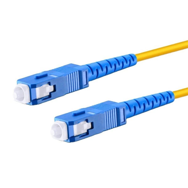
Of the more than a dozen types of fibre-optic connectors available, the four most commonly used today are LC, SC, FC, and ST. Fiber connector types LC, SC, FC, ST, MTP, and MPO are widely used in past and present. What are the differences between them? Who is the most popular one? Find the answer in the article. What is a Fiber Connector? The optical fiber connector is a kind of detachable passive optical component used. Fiber optic connectors are the unsung heroes of modern networking. They are small, often overlooked components, yet they are essential for ensuring high-speed, low-loss, and reliable optical transmission. In addition to serving the same general function, the four connectors differ in size, locking mechanism, and best applications. The following guide systematically describes. Choosing the right connector for an optical link is one of those small decisions that has outsized effects on installation density, reliability, and long-term maintenance. broadband connection is available everywhere. Its. Optical fiber terminations are the mechanical and optical interfaces that connect fiber cables to equipment, patch panels, and network hardware. They directly affect insertion loss, return loss, reliability, and long-term network stability. In this guide, we break down the most common optical fiber.
[PDF]

In this guide, you'll learn how to create rack diagrams that are accurate, scalable, and easy to maintain—so you can plan smarter, troubleshoot faster, and keep your infrastructure organized. This guide will explore the cost breakdown for rack and stack solutions, factors that influence pricing, and how companies can optimize their setup costs for maximum efficiency. Additionally, we will take a closer look at Digital Infotech Solutions, a leader in providing custom rack and stack. Most data center colocation providers hide pricing behind request-for-quote (RFQ) processes. You contact them, wait three to five business days, and only then learn whether colocation fits your budget. This opacity makes it nearly impossible to benchmark costs, negotiate terms, or plan. Whether you're planning a new deployment, reorganizing a rack, or documenting existing infrastructure, a clear visual layout keeps everyone aligned and prevents costly mistakes. Visit our free and simple network rack planning tool to create and export your rack. No registration or download required. Just follow this link and start designing in our pre-designed Server Rack Diagram Template. Before you. A rack diagram is a two-dimensional elevation drawing showing the organization of specific equipment on a rack. It provides a clear overview of the physical layout of the rack, including the placement and positioning of servers, switches, storage devices, and other.
[PDF]

This guide will explain their functions, discuss the role of single-mode LC connectors in modern fiber optic systems, and present the logic for their adoption on a broader scale. Proper connection of fiber optic cables is essential to harness these benefits fully, as even minor errors can lead to significant performance issues like signal loss. This article will guide you through the necessary tools, materials, and methods on how to connect fiber optic cables effectively. Fiber optic internet delivers blazing-fast speeds and reliable connectivity, making it a top choice for modern homes and businesses. In this guide, we'll walk you through how to. In this article, we'll explain how to connect multiple Ethernet switches using fiber optic cables and the equipment required for this to work. Network topology refers to the way in which the links and nodes of a network are arranged in relation to each other. There are also fiber-to-fiber versions that translate between different fiber types, wavelengths, or distances. Common families support 10/100/1000 Ethernet and. This is where single-mode fiber optics comes in. Single-mode fiber is being viewed as the backbone of enterprise connections, and it is used to facilitate all 400G solutions and real-time AI solutions/applications, due to its ability to transmit data over long distances with minimal signal loss.
[PDF]
The term host bus adapter (HBA) may be used to refer to a interface card. In this case, it allows devices in a Fibre Channel to communicate data between each other – it may connect a server to a switch or storage device, connect multiple storage systems, or connect multiple servers. Fibre Channel HBAs are available for, computer architectures, and buses, i.
[PDF]
