This comprehensive guide will explore the importance and benefits of this integration, provide an understanding of fiber optic cable and Ethernet ports, discuss their compatibility, and offer a step-by-step process for connecting them. Proper connection of fiber optic cables is essential to harness these benefits fully, as even minor errors can lead to significant performance issues like signal loss. This article will guide you through the necessary tools, materials, and methods on how to connect fiber optic cables effectively. But here's the thing: how you connect fiber optic cable really matters. A shaky connection means weaker signals, dropped streaming, or slow uploads. Get the hookup right, and you'll enjoy streaming, gaming, and video calls without interruptions. Fiber optic cables need careful handling. Unlike. The process to connect fiber optic cable to router requires careful attention to detail, but I'll walk you through every critical step with the precision and clarity you deserve. Why Use Fiber Optic Internet? Before diving into the setup, let's quickly recap why fiber optics are worth the effort: Lightning-fast speeds (up to 1 Gbps or higher). Low latency for. Connecting a fiber optic cable to an Ethernet network involves a few key steps and requires some specific hardware to ensure a seamless transition between these two different types of network mediums.
[PDF]
While a cut or damaged fiber optic cable can temporarily take your network down, it is possible to quickly fix the cable with the right tools. This wikiHow article will teach you how to splice a cut fiber optic cable back together with a fiber optic stripper and cutter and a fiber. To connect your fiber optic cable to a router, ensure you have the following: Fiber optic modem (ONT): Most fiber connections require an Optical Network Terminal (ONT), provided by your ISP. Compatible router: Verify that your router supports fiber optic input (look for an SFP or WAN port labeled. The fiber optic cable does not plug directly into a standard home router because the signal type must be translated. The fiber line terminates at the Optical Network Terminal (ONT), which is typically supplied and installed by the internet service provider. This specialized equipment serves as the. The process to connect fiber optic cable to router requires careful attention to detail, but I'll walk you through every critical step with the precision and clarity you deserve. Here's a step-by-step guide to help you through it. Understand the Basics Before diving in, familiarize yourself with the components involved:. See you soon! 🚀 How to connect a fiber optic cable to the router. Check compatibility: Before you begin, make sure your router supports fiber optic connection. Not all routers can connect directly to a fiber cable, so it is important to verify this information before continuing.
[PDF]
In this report, modeling and experimental results are presented for three fiber Bragg gratings that were fabricated in Newport F-SMF-28 fiber with the direct-write method. The model is based on coupled-mode theory assuming weakly guiding fibers. Optical sensors based on Fiber Bragg Gratings (FBG) are becoming increasingly popular. They are easy to install, immune to electromagnetic interferences and can also be used in highly explosive atmospheres. But just how does a fiber Bragg grating work? Our experts answer this and other questions. One of the particularly useful applications of a direct-write method is for the fabrication of fiber Bragg gratings (FBGs). The. The Bragg grating acts like a mirror which only reflects one very precise wavelength (colour). When the optical fibre is strained or when its temperature changes, the reflected wavelength varies proportionally. Different sensors manufactured using gratings with a specific wave length can be.
[PDF]
This guide covers the essential tools and step-by-step procedures for low-loss fiber optic cable repair. Fiber optic cables are the backbone of modern networks, delivering fast and reliable data transmission. Accidental cuts, breaks, or other damage can disrupt your network and cause costly downtime. With the right tools and techniques, you can efficiently repair damaged fiber cables and restore. While a cut or damaged fiber optic cable can temporarily take your network down, it is possible to quickly fix the cable with the right tools. This wikiHow article will teach you how to splice a cut fiber optic cable back together with a fiber optic stripper and cutter and a fiber optic crimper. This complete guide covers everything from identifying causes of failure to advanced repair techniques, drawing on the latest industry standards and innovations. Begin by identifying the damage, which can be done using an Optical Time Domain. When fiber cables sustain damage, specialized repair techniques help restore connectivity and maintain data integrity. The actual steps may vary depending on the cable and/or connectors.
[PDF]

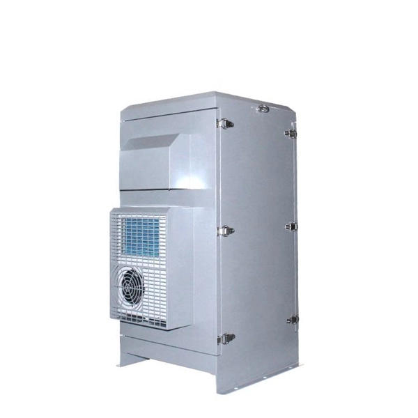
Set your fiber optic-to-Ethernet converter box in a location near your Ethernet switch and plug in its power adapter. Insert the end of your fiber optic network line into the fiber optic connector on the converter box. Fiber optic cabling is increasingly used to connect network switches and other datacom equipment, especially in long-distance and mission-critical applications. Fiber provides: Increased internet signal bandwidth. Most modern fiber-enabled network switches require an SFP transceiver module. This is a cost-effective and high performance way to connect network switches. Advantages Determine the length of the fiber run and choose either multi mode for runs under 1000 feet or single mode for runs over 1000 feet. SFP transceiver modules are specific to the type of fiber being connected. Connecting a switch to a fiber optic network involves several steps and requires specific equipment to ensure a successful and efficient connection. This guide will. In this article, we'll explain how to connect multiple Ethernet switches using fiber optic cables and the equipment required for this to work. Network topology refers to the way in which the links and nodes of a network are arranged in relation to each other. Ethernet ports are designed for copper cables (like Cat5e or Cat6), which transmit data using electrical signals. You need a media converter or a.
[PDF]
Fiber optic cables, from the outside at least, don't look drastically different from many other kinds of cabling, since their outermost layer tends to be a colored plastic or silicon tubing. It's common for them to.
[PDF]
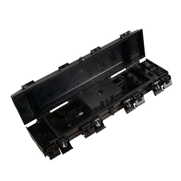
Dual door fiber enclosures provide our highest level of distribution panel security. They give you the option to separately lock the network and distribution doors for more control over panel access. The second doo.
[PDF]

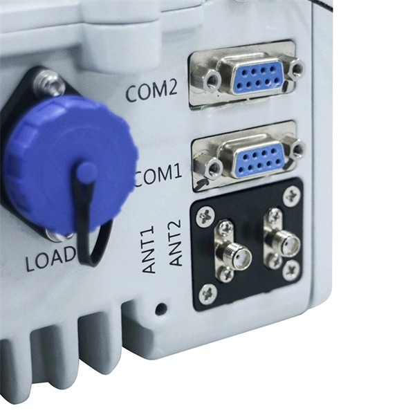
The short answer is no - RJ45 connectors are designed for electrical Ethernet signals, while fiber optics transmit light pulses through glass or plastic. However, modern networks often combine both technologies. Traditionally, network switches have been connected using copper cables, but with the increasing demand for high-speed and reliable connectivity, fiber optic cables have gained prominence. If you plan to upgrade to fiber optic network or blend fiber optics into your existing legacy network, you will require a fiber optic. Fiber optic cables are often seen as the gold standard for network cabling. Unlike copper wires, which are limited by lower data transmission speeds, shorter transmission distances, and higher susceptibility to electromagnetic interference, fiber optic cables offer unparalleled performance and can. Briefly, an ONT is a modem that uses optical fiber cables that bridge the internet connection from an ISP (internet service provider) to the end user of fiber internet, while Ethernet cables are used to connect the ONT device to your router that provides internet in your home and offices. Other than entry level network switches, most of today's network switches include one or more GiBC (Gigabit Converter) or SFP (Small Form-factor Pluggable) slots. SFP modules insert into these slots and and require two strands of fiber, typically duplex Using multi mode fiber (for runs under 1000.
[PDF]

OSFP, or Octal Small Form-factor Pluggable, is a high-speed transceiver form factor designed for next-generation data center networking. Compared with previous generations of optical modules, OSFP is optimized for higher bandwidth, better thermal performance and denser port. Among the various 400G optical transceiver form factors, OSFP stands out as a next-generation form factor specifically designed for high-speed Ethernet, offering clear advantages. This article introduces the fundamental concept and key characteristics of 400G OSFP Ethernet optical transceivers, and. Optech, a Taiwan-based optical transceiver manufacturer, provides professional 400G OSFP and 800G OSFP solutions designed for AI, cloud, high-performance computing, data center and advanced networking applications. Understanding MSA is critical for compatibility validation, cost. As data centers transition from 400G to 800G interconnects, bandwidth demand, power efficiency, and thermal constraints have forced the industry to look beyond traditional form factors. Designed to support 400 Gigabit Ethernet transmission with improved thermal performance and higher power capacity, OSFP modules are widely adopted.
[PDF]
Building an Efficient Fiber Infrastructure. The ATB3120-S-8 ADU (Active Distribution Unit) is an active optical device used to connect the main FTTR and the sub FTTR. It provides optical signals and power input for the sub FTTR. The products can be installed in an indoor information box or on a. Huawei includes the HUAWEI eKit ATB3120-S-8 Optical Socket in its MiniFTTO optical access portfolio. This device works as an optical socket used in FTTR and MiniFTTO fiber distribution systems. 0 solution uses two transformative technologies to support five typical network scenarios. In the earliest FTTH solution, ODN 1. 0 optical splitting was used for. 124 Available: Delivery 2-3 Business Days The Huawei ATB3120-S-8-XC/UPC-2 ADU is a cutting-edge optical distribution unit designed to enhance network performance with precision and reliability. This advanced device provides seamless fiber optic distribution, accommodating up to eight connections.
[PDF]

Aggregation switches are widely deployed in high-traffic environments, such as enterprise backbones, data centers, and large campus networks, where they serve as a bridge between the access and core layers. This document provides campus networks typical configuration examples and feature typical configuration examples. "Campus Networks Typical Configuration Examples" provides typical campus network networking modes and a variety of deployment examples. It works by designating a device to allow the aggregation of multiple test access points and to connect to multiple monitoring systems. TAP aggregation switches link. What Is an Aggregation Switch? An aggregation switch is a network device that consolidates traffic from multiple access switches, wireless access points, or other edge devices and forwards it to core switches or routers. By bundling multiple network connections into a single high-bandwidth link. This guide provides information and guidance to help the network administrator deploy the Meraki Switch (MS) line in a Campus environment. Campus networks typically adopt a tiered design, scaled according to the specific needs of the individual campus. This arrangement increases throughput beyond what a single relationship could. IEEE 802. 3ad link aggregation enables you to group Ethernet interfaces to form a single link layer interface, also known as a link aggregation group (LAG) or bundle. The LAG balances.
[PDF]
Security system integration is the process of combining security devices for surveillance, threat detection, and access control into a single, interconnected system. Securitas Technology provides integrated security system solutions for thousands of commercial buildings and corporate campuses in North America. Our. Security Systems and Integration Solutions | L3Harris® Fast. L3Harris' extensive expertise and knowledge supporting system integration is built upon a rich history in the defense, space, civil government and cybersecurity markets with exceptional past performance in security and. Security isn't just about adding more systems — it's about making them work together. We've spent decades addressing. Integrating security systems consists of connecting different technologies (such as CCTV cameras, presence sensors, alarms, access control, remote gates, lighting and app monitoring) so that they work in a coordinated way, sharing data and responding automatically to events. Look Beyond. Get secure operations, seamless scaling, and expert-led Microsoft Copilot Implementation and 24/7 Managed SOC Services. Your business deserves IT that just works. We offer guaranteed outcomes: high reliability, minimal downtime, and strategic maintenance. We free your internal teams to focus purely.
[PDF]

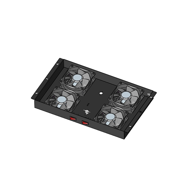
The mounting height of a network rack typically ranges from 24 inches to 84 inches (2 to 7 feet), depending on the equipment and installation requirements. A server rack is more than just a physical frame—it determines how well your rack servers, network switches, PDUs, and storage arrays can be organized, cooled, and maintained. Selecting the right rack size ensures not only compatibility with today's hardware but also room for future expansion. The. Common server rack sizes are 19‑inch width, heights like 42U or 48U, and depths from ~24″ to 48″. Choose size based on equipment type, cooling, space, and future growth. Most IT environments default to 42U, 19-inch width, and 1000–1200 mm depth unless space constraints or special equipment dictate. A rack unit, abbreviated as “U,” is the standard unit of measurement for the height of devices designed for rack mounting. One rack unit equals 1. Important: U describes height only, but a server's real "capabilities" are also determined by chassis depth, internal layout, airflow, rails, power, and expansion (PCIe/risers, NVMe. You'll get precise, vendor-agnostic dimensions for standard server rack sizes—including exact width (19″ internal / 24″ external), height (42U = 73. 5″), depth (24″–48″), and the universal 1U = 1. 75″ rule—plus how to verify usable space, avoid common fitment errors, and select based on equipment.
[PDF]