
When it comes to testing fiber optic cables, a Visual Fault Locator (VFL) is an essential tool in your toolkit. A VFL is used to detect faults, breaks, or bends in fiber optic cables by emitting a bright red light that is visible even through the fiber's jacket. Let's dive into everything you need to know about mastering VFLs. It's a cost-effective and. Visual Fault Locator (VFL) testing is one of the most fundamental inspection methods used in FTTH, ODN, and data center environments. A VFL emits a visible red laser (typically 650 nm) that travels along the fiber core and leaks out at points of excessive loss, fiber breaks, or microbends. Although. The Fiber Visual Fault Locator Kit is an essential tool for network technicians and engineers; it provides an accurate and quick method of finding such problems as breaks, bends or faults that may affect the network's operation. It works by injecting a visible red laser light (usually in the 650nm wavelength) into the fiber. When the light encounters a fault, such as a break, bend, or bad splice, it leaks out of the fiber, making the. Conducting efficient, repeatable fiber optic cable certification requires an array of specialized test equipment: Optical Loss Test Set (OLTS) – Integrates adjustable light source and power meter for efficient, Tier-1 insertion loss testing. Visual Fault Locators – Handheld devices projecting.
[PDF]

The optical power meter is similar to the voltohmmeter in application but measures the optical resistance (losses measured in dBm or dBM) of a cable before and after installation and provides a comparative analysis of the splices. The range of the meter is adjustable. Regularly testing fiber optic cables helps minimize network downtime, lengthens the network's longevity, reduces maintenance requirements, and helps support network reconfiguration and upgrades. These factors significantly add to the fiber optic network's long-term performance, manageability, and. Several types of tests are commonly conducted to assess and maintain the health of fiber optic networks. Continuity testing verifies that the fiber is intact and that light can pass through from one end to the other without any blockages. These test procedures assess the physical and functional qualities of fiber optic cables, connectors, and the network as a whole. Key tests include: Effective fiber testing utilizes advanced tools such as Optical. One way to test a splice is to use an Optical Power Meter. As the components like fiber, connectors, splices, LED or laser sources, detectors and receivers are being developed, testing confirms their performance specifications and helps. Regular testing of fiber optic cables is not just a preventive measure; it's an investment in the longevity and efficiency of your network. By identifying potential issues early, you can enhance.
[PDF]

This helps keep fiber optic cables safe from harm and signal problems when you put them in. Use the right lubricant. Follow the rules for tension and bend radius. Try new methods like air blowing. Use smart. Fiber optic cable is strong, reliable and built for long-term performance, but it still needs to be handled correctly during installation. This article explores recommendations for pulling and installing fiber optic cable. Most fiber optic cables boast a pull strength of 100 – 200. Fiber optic cable and copper twisted-pair cable may seem alike at first glance. Both types come in a coil or on a reel and are typically installed in the same areas with similar tools and techniques. Yet the materials differ greatly. A copper wire can take a twist with little worry, but glass. Installing fiber optic cable requires precision, skill, and a commitment to safety, especially when using powerful underground cable pullers. While these tools boost efficiency, their complexity introduces risks that demand proactive management. This guide provides a comprehensive overview of. When deploying fiber links in data centers, LANs, or even in outside plant networks, fiber is pulled between equipment and spaces through pathways, cable managers, cable tray, risers, or conduit. This makes sure the cable pull is smooth and safe. Use smart monitoring devices.
[PDF]
Our extensive offering of fiber optic cables, connectors, cassettes, enclosures, patch cords, cable assemblies, cable distribution products and accessories deliver high performance, reliability, and scalability. Precision Fiber Products, Inc. offers a wide range of fiber optic products. We specialize in fiber optic interconnect components, including fiber optic cables, connectors, cable splicing, ferrules, and more. Ready to get started? Get a quote now! In just a few steps, you can receive a quote. ESTABLISHED IN 1976: Selected three times as an "INC 500" company. Designated as one of the "Hottest VAR/Distributors". Delivering high performance, reliability, and scalability, the Base-16 Fiber Cabling. Belden's extensive line of indoor and outdoor cable products is offered in tight buffer and loose tube designs. Armored, burial, and ruggedized designs are suited to a host of industrial environments. For each product design, items for OM1, OM3, OM4, OM5, and OS2 (Singlemode) items have been. Cables. com (Datacomm Cables, Inc. ), is headquartered in Long Island, New York (Deer Park, NY). Since 2001, Datacomm Cables has been a single source offiber optic cables,networking cables,power cords,crypto cables, datacenter cables,Cat5 cables,Cat6 cable,Cat6A cable,shielded cables,outdoor cables.
[PDF]
A cable management rack is designed to route, protect, and organize copper and fiber cables inside network cabinets. Beyond keeping cables tidy, a well-structured cable manager reduces cable stress, improves heat dissipation, and ensures bend-radius compliance for data transmission. This article provides a clear technical view of cable management racks, their structures, and how to select the right solution for modern networks. Cable management in server racks simply refers to organizing, routing, and securing power and data cables so they stay neat, accessible, and. Simply put, a cable rack is a structured set of shelves designed to organize, protect, and manage cables in various settings. These racks range from simple, affordable options to complex, high-capacity models that accommodate a vast number of cables. The benefits of using cable racks are numerous. Horizontal cable management is a cornerstone of efficient IT infrastructure, ensuring that server racks and enclosures remain organized, accessible, and functional., Ethernet, fiber optic, coaxial). At its core, it aims to: Minimize cable tangling, kinking, and wear. Simplify troubleshooting and maintenance. As businesses increasingly rely on robust network infrastructure, proper cable organization becomes critical for.
[PDF]
This article will guide you through the process of troubleshooting fiber optic connections, with a focus on ensuring proper TX and RX alignment and how to correctly switch patch cables to resolve issues. Proper connection of fiber optic cables is essential to harness these benefits fully, as even minor errors can lead to significant performance issues like signal loss. When issues like signal loss, slow speeds, or intermittent connectivity arise, systematic troubleshooting is key. This guide will walk you through diagnosing and resolving common. The process to connect fiber optic cable to router requires careful attention to detail, but I'll walk you through every critical step with the precision and clarity you deserve. This comprehensive guide combines industry standards with field-tested practices to ensure you achieve a rock-solid. Fiber optic cables are widely used in modern networks for their high-speed data transmission capabilities and resistance to electromagnetic interference. However, like any other networking technology, fiber optics can encounter issues that disrupt communication. One of the most common problems in. Fiber optic internet delivers blazing-fast speeds and reliable connectivity, making it a top choice for modern homes and businesses. Their ability to transfer large amounts of data at lightning speed makes them a go-to for efficient communication. Knowing how to avoid signal loss in.
[PDF]

It's important to watch the supply reel while installing to ensure the minimum bend radius isn't compromised. Use proper cable pulling lubricants. Sequentially mark the pulling role for easy identification. Use extreme caution when removing the pull eye. Fiber optic cable is surprisingly strong, durable and pliable; however, several best practices should be followed to ensure a successful cable installation. This article explores recommendations for pulling and installing fiber optic cable. Most fiber optic cables boast a pull strength of 100 – 200. That's where investing in high-quality patch cords makes a real difference—they arrive with better polishing, protection caps, and lower insertion loss, reducing the margin for error during deployment. When discussing installation mistakes, endface contamination deserves special attention because. Fiber optic troubleshooting is an essential skill for network administrators, technicians, and engineers responsible for maintaining and repairing fiber optic systems. These high-speed, high-capacity communication networks are increasingly replacing copper cables, offering superior performance and. Harnessing the full potential of fiber optics hinges greatly on the quality of its installation. During installation, all curvatures should be smooth. The cable should be bent as little as possible. Most fiber damage does not come from normal operation after the system is live.
[PDF]
The Open Systems Interconnection (OSI) model is a developed by the (ISO) that "provides a common basis for the coordination of standards development for the purpose of systems interconnection." In the OSI reference model, the components of a communication system are disting.
[PDF]

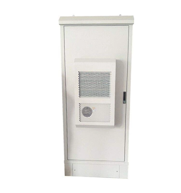
In telecommunications, a base station is a fixed transceiver that is the main communication point for one or more wireless mobile client devices. It further connects the device to other. A communication base station is composed of a computer room, base station, antenna, feeder line (transmission line between transmitter and antenna), and supporting equipment. The antenna is at the top of the signal tower, and below the tower is a computer room. Along with increased capacity demands driven by the explosion of cloud and connected device growth, engineers need interconnects that enhance the design. A base transceiver station (BTS) or a baseband unit (BBU) is a piece of equipment that facilitates wireless communication between user equipment (UE) and a network. UEs are devices like mobile phones (handsets), WLL phones, computers with wireless Internet connectivity, or antennas mounted on. Fiber Optic Cables: High-speed fiber optic cables connect the BBU to the RRUs (RE part). Signal Transmission: The optical signals carry data, control, management, and synchronization information. Topology: The BBU and multiple radio heads can be connected in cascade or star configurations. The rise. The design investigates the possibilities of Free-Space Optical (FSO) communication systems and MilliMeter-Wave (MMW) technologies operating at 60. Although these technologies are highly effective and have a high throughput, they are nevertheless vulnerable to weather phenomena like rain.
[PDF]

Fiber optic terminal boxes provide functions such as input, branching and splicing of optical fiber cables. Through the connectors and splicing boxes in the terminal box, optical fibers can be quickly connected and repaired. Serving as a critical connection point, FTB facilitates the termination, splicing, or connection of fibers from various cables to other network devices such as switches, routers, or Optical Network Terminals (ONTs). It aids in splicing, splitting, storing, and managing fibers within the appropriate. The optical fiber terminal box is the terminal joint of an optical cable, one end of which is an optical cable, and the other end is a pigtail, which is equivalent to a device that splits an optical cable into a single optical fiber. A fiber pigtail is a specific hardware connection used for cable termination. It is a small enclosure that can house and protect the fiber optic cables, splices, and connectors. The optical fiber termination box and optical fiber splice box serve distinct purposes and are not interchangeable.
[PDF]

In this informative guide, we'll walk you through the step-by-step process of stripping and preparing fibre optic cable for termination, covering techniques, tools, and best practices to help you achieve successful terminations in your fibre optic installations. Strip the jacket and buffer: Using a fiber optic cable stripper, remove the outer jacket and buffer tubes from the cable. Make sure to strip the appropriate length, as specified by the manufacturer. Be cautious not to damage the fibers during this process. Cleave and cut the fibers: After. In this instructional video, Bob Licari, Test Equipment Product Manager, demonstrates a simple way to strip optical fiber. more Audio tracks for some languages were automatically generated. Eventually, this imperfection can initiate a crack when the. It is impossible to work in fiber optics without having a good working knowledge about cables and skills in pulling, placing and preparing cables for termination and splicing. Properly stripping the cable and preparing the fibre ends ensures a clean and secure connection, leading to optimal signal transmission and network performance. Terminating fiber optic cables essentially means putting connectors on fiber optic cable so that you can connect the cable to various devices or network components. Think of it as the equivalent of connecting the dots in a complex puzzle; without proper termination, the whole system can break down.
[PDF]

The manufacturing process of fiber optic cables involves several crucial steps, including fiber production, cable assembly, testing and quality control, and packaging and distribution. Each step ensures that the cables are produced to the highest standards and can efficiently. The digital revolution continues to drive unprecedented demand for high-speed, reliable data transmission. At the heart of this transformation lies fiber optic cable manufacturing, a precise and sophisticated process that powers our interconnected world. With the global fiber optic market reaching. Fiber optic cables are the backbone of today's high-speed internet, telecommunication systems, and data transfer technologies. Unlike traditional copper cables, fiber optic cables use light signals to transmit data, which allows them to carry large amounts of information at extremely high speeds. The production of optical fiber is a precision-driven process that transforms raw materials like silicon tetrachloride into ultra-thin, high-performance fibers capable of transmitting terabits of data over thousands of kilometers. With the increasing demand for faster and more reliable connectivity, the construction of optical fiber cable factories has become essential. This hair-thin strand of glass or plastic transmits data as pulses of light over long distances with minimal signal loss. The first step in.
[PDF]

No, single-mode SFPs are designed to work with single-mode fiber cables and multimode SFPs are designed to work with multimode fiber cables. Attempting to use a single-mode SFP with a multimode fiber cable could result in poor network performance or data transmission errors. It utilizes ultra-low optical attenuation for medium to long transmission. The single mode SFP generally uses high-cost FP and DFB lasers with long wavelengths to optimize. Single-mode (SMF) and multi-mode fiber (MMF) use different core sizes, sources and wavelengths. Understanding the compatibility constraints prevents costly downtime and troubleshooting. To address this question, it's important to understand the characteristics of both single-mode and multimode fiber optics, as well as the implications. Multimode fiber (MMF) uses a larger core diameter (typically 50 or 62. 5 microns) allowing multiple light modes to propagate, suitable for short distances. In contrast, single mode fiber (SMF) has a smaller core diameter (~9 microns) supporting one mode of light, enabling longer reach with minimal. SFP modules are compact, hot-swappable devices used in networking equipment to facilitate the connection of fiber optic cables. They come in two primary types: single-mode and multimode. Single-mode SFPs are designed for long-distance communication, typically using a laser as the light source, and.
[PDF]
