The fiber connector types, sometimes referred to as terminations, link fiber optic cables together through terminals, switches, adapters, and patch panels, by bridging the gap between their internal glass fi.
[PDF]
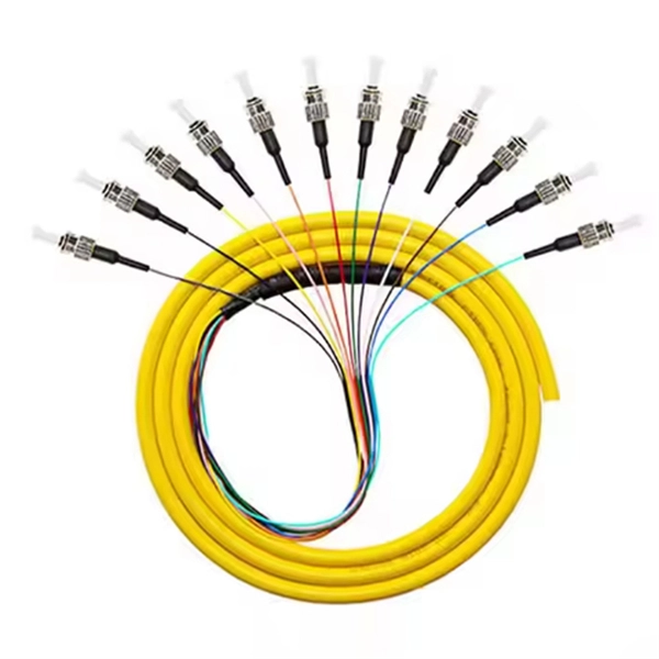
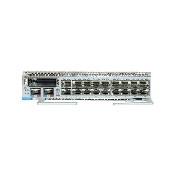
Huawei switches support optical modules of the following encapsulation types: CFP, QSFP+, QSFP28, XFP, SFP, eSFP, and SFP+. All optical modules are hot swappable. SFP: small form-factor pluggable. eSFP: enhanced small. Optical fiber active connectors: Optical patch cords, optical fiber connectors, optical fiber patch cords, Optical splitter: Optical fiber coupler, optical splitter, fused coupler, fused taper, planar waveguide optical splitter, plc splitter, coupler, blade type, box type, rack type, lgx, Fiber. Optical modules are important devices in fiber optic communication systems. and originated in Shenzhen. Huawei Technologies Co. is a telecommunications network solutions provider. Huawei's main business scope is switching. Optical modules are available in various types to meet diversified requirements. Depending on transmission rates, optical modules are classified into 100GE, 40GE, 25GE, 10GE, FE, and GE optical modules. 02315233 - Genuine Huawei SFP-FE-SX-MM1310 Optical Transceiver, SFP, 100M/155M, Multi-mode Module (1310nm, 2km, LC)Basic InformationModule name: SFP-FE-SX-MM1310Part Number: 02315233Model: SFP-FE-SX-MM1310Form factor: SFPApplication standard: 100BASE. Optical. The purchased products, services and features are stipulated by the contract made between Huawei and the customer. Unless otherwise specified in the contract, all.
[PDF]
In its most common form, a cube, a beam splitter is made from two triangular glass which are glued together at their base using polyester,, or urethane-based adhesives. (Before these synthetic, natural ones were used, e.g.) The thickness of the resin layer is adjusted such that (for a certain ) half of the light incident through one "port" (i.e., face of the cube) is and th.
[PDF]
Fibre Channel switches can be divided into two classes. These classes are not part of the standard, and the classification of every switch is a marketing decision of the manufacturer: Directors offer a high port-count in a modular (slot-based) chassis with no single point of failure (high availability).Switches are typically smaller, fixed-configuration (sometimes semi-modular), less redundant devices. OverviewFibre Channel (FC) is a high-speed data transfer protocol providing in-order, lossless delivery of raw block data. Fibre Channel is primarily used to connect to in (SAN) in co. When the technology was originally devised, it ran over optical fiber cables only and, as such, was called "Fiber Channel". Later, the ability to run over copper cabling was added to the specification. In order to avoid confu.
[PDF]

Explore the top 6 stainless steel enclosure manufacturers in Egypt, offering robust solutions for electrical systems in various sectors for enhanced safety and efficiency. A Complete offer for all environmental conditions. Schneider Electric is a leading name in enclosure design. We have been protecting your. KSA was Approved from Schneider Electric to be Eco Expert in Low Voltage Panels and produce TYPE TESTED Panels. KSA has become an Approved Eco Expert in Power Distribution. Establish a striking presence, a better power management, or elevate your project through our products. Our Type Tested LV. Wall-mounted enclosure of fiberglass-reinforced polycarbonate with either grey or transparent cover. Protection category IP 66. Covers feature quick-release fasteners for speedy maintenance. Self-extinguishing material for safety. Wall-mounted enclosure with cover made from sheet steel, available. Our ODF systems are designed to streamline and organize optical fiber connections within data centers, telecommunications facilities, and enterprise networks. QNAP TS-832PX-4G 8-Bay Cloud Storage NAS Enclosure (Diskless) QNAP TS-832PX-4G 8-Bay Cloud Storage NAS Enclosure (Diskless) QNAP TS-832PX-4G 8-Bay Cloud Storage NAS Enclosure (Diskless) Notice: Please confirm price & availability before submitting your order due to unstable prices and shipping.
[PDF]

There are four main types of telecommunication towers: lattice towers, monopole towers, guyed towers, and stealth towers. These towers play a crucial role in enabling wireless communication by providing a platform for the installation of radio equipment and antennas. Modern communication tower technology & infrastructure represents the essential physical backbone of our global wireless world. This specialized field combines civil, structural, and electrical engineering to create the tall structures that support antennas for mobile networks. As wireless services. Telecommunication networks form the backbone of modern connectivity, supporting mobile communication, data transmission, broadcasting, and emerging technologies such as 5G. At the core of these networks are tower structures designed to carry antennas, microwave dishes, and transmission equipment. With the rapid development of mobile communications, the Internet of Things, and 5G technologies, communication towers play a vital role in modern information infrastructure. As the industry advances, various types of telecom towers have been developed, each tailored. Due to the rising popularity of cell phones over the last 15 years, communication towers can now be located almost anywhere you look. However, it's important to note that not all cell towers are the same. Telecom towers are typically classified based on their structural form and placement, allowing wireless carriers to deploy networks efficiently.
[PDF]

Huawei routers support optical modules of the following encapsulation types: SFP, eSFP, SFP+, XFP, and QSFP+. SFP: small form-factor pluggable. SFP optical modules support LC fiber connectors and are hot swappable. Optical modules are available in various types to meet diversified requirements. Depending on transmission rates, optical modules are classified into 100GE, 40GE, 25GE, 10GE, 2. 5GE, FE, and GE optical modules. 02315233 - Genuine Huawei SFP-FE-SX-MM1310 Optical Transceiver, SFP, 100M/155M, Multi-mode Module (1310nm, 2km, LC)Basic InformationModule name: SFP-FE-SX-MM1310Part Number: 02315233Model: SFP-FE-SX-MM1310Form factor: SFPApplication standard: 100BASE. 02315205 - Genuine Huawei eSFP-FE-LX-SM1310. Optical modules are important devices in fiber optic communication systems. Huawei Optical Module is manufactured by Huawei Technologies Co. and originated in Shenzhen. is a telecommunications network solutions provider. Huawei's main business scope is switching. Those are SFP (Small Form-factor Pluggable) slots, and the tiny modules that go into them are what make fiber networking actually work. Here's the thing: there are a LOT of different SFP modules out there. GPON SFP sticks, Bidi SFPs, standard duplex SFPs, SFP+ for 10G — and they all look almost. The SFP+ and XFP optical modules are 10GE hot-swappable optical modules. Compared with the SFP+ optical modules, the XFP optical modules have a larger caliber.
[PDF]

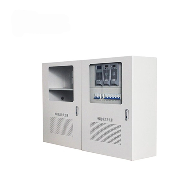
We'll explain what they are, the different panel types you'll encounter, NEC 408 requirements that govern their installation, and common applications for each type. Distribution panels, breaker panels, load center, and/or distribution boards—any name you call them, they're a key part of every electrical system. Wiring distribution panels serve as the central hub and nerve center, routing power from the main service feed to multiple circuits. When setting up. In the world of electrical installations, the term DB box —short for Distribution Board box —refers to the central unit that distributes incoming electrical power to multiple outgoing circuits in a building. Whether you're powering up a residential home, a commercial office, or an industrial plant. Electrical Wiring is a process of connecting cables and wires to the related devices such as fuse, switches, sockets, lights, fans etc. to the main distribution board is a specific structure to the utility pole for continues power supply. It receives power from the main electrical supply and divides it into separate circuits, each. A distribution box, or DB box, is a circuit breaker enclosure. It is a vital part and central hub of any electrical system. It is for the economical use of wiring conductors inside, and outside of a room or building with better load control. Cleat Electrical wiring 2.
[PDF]

Common methods of protecting busbars include overcurrent-based interlocking schemes, overcurrent-based differential protection, high-impedance differential protection, and percentage differential protection. Interlocking and overcurrent differential protection can be implemented with any suitable. DEFINITIONS. IV EXECUTIVE. Busbar Differential Protection Definition: Busbar differential protection is a scheme that quickly isolates faults by comparing currents entering and leaving the busbar using Kirchoff's current law. Current Differential Protection: This protection method connects CT secondaries in parallel and. Busbars play an important role in power transmission and distribution. They are employed as a central distribution point for all feeders. The problem is that the busbars. Busbars have typically been left without dedicated protection, from the following reasons: It is a fact that the risk of a short circuit happening on modern metal clad equipment is insignificant, but it cannot be completely dismissed. Nevertheless, the damage resulting from one short circuit may be. 25 kV insulation is required. These heat-shrinkable tubes for straight and bent busbars are extremely flexible, allowing them to be easily positioned on busbars and quickly instal ed using a gas torch or oven. They have a high expan-sion ratio, so each size of tubing fits a range of busbar sizes.
[PDF]

This video shows real on-site footage of electrical installation, demonstrating safe and standardized wiring methods used by professionals. more Learn how to wire a distribution box step by step!. Temporary power systems are essential for construction projects, yet they often introduce serious safety risks. Loose wiring, exposed connectors, and unstable electrical connections can cause shocks, equipment failures, or costly downtime. This article examines how modern portable power cabinet. work requires electrical power for many purposes. However, exposure to weather, frequent relocation, rough use and other condi-tions not normally encountered with conventional wiring systems necessitate special consideration not require in other applications or in completed structures. The. Metal raceways, cable armor, and other metal enclosures for conductors shall be metallically joined together into a continuous electric conductor and shall be so connected to all boxes, fittings, and cabinets as to provide effective electrical continuity. The requirements of Article 590 apply to temporary power and lighting installations and removals, including. Learn what OSHA requires for temporary wiring on construction sites, from grounding and GFCI protection to overhead clearances and employer liability. Temporary wiring on construction sites must comply with the electrical safety standards in 29 CFR 1926, Subpart K. These federal rules, enforced by.
[PDF]
Step-by-step cable tray and conduit installation method with safety, quality and inspection procedures as per IEEE standards. But before you lay the first tray or clamp down a single cable, you need a solid plan. This guide breaks down the process step by step. Plan the Route Before You Drill No installation should start without a plan. Mark the cable tray route based on your electrical cable tray design and site. This guide covers the critical steps, from selecting the right electrical cable tray and performing accurate cable fill calculations to managing a safe cable pull through and ensuring all bonding and grounding requirements are met. For licensed electricians, mastering these principles is essential. This method statement describes a detailed procedure for properly installing cable trays and conduits for the Feeder System. The objective is to ensure safety, quality and compliance during the. Below is the detailed cable tray installation method statement not only for cable tray but also applicable for GI ladder and trunking for indoor and outdoor applications and in service rooms like pump rooms, electrical rooms and plant rooms etc. The Cable Tray system is installed in electrical rooms, plant rooms, and service corridors. The key requirements for cable tray installation include: Incorrect installation can lead to overheating, cable damage, or system failure. This is why proper planning and execution are.
[PDF]

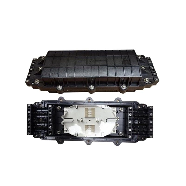
Learn how to install a fiber optic termination box step-by-step for FTTH projects. Covers mounting, splicing, routing, labeling, and testing for indoor/outdoor use. Installing a fiber optic termination box is one of those jobs that looks simple on paper. A fiber termination box is the standard instrument used in fiber optic networks to connect, secure, and protect optical fibers at the terminating point. Proper installation and maintenance of FTBs are essential to ensure the reliability and performance of the network infrastructure. Before. FTTP or fiber To The Premises applications have reinforced the importance of reliable and stable fiber optic terminations. Good quality fiber laying and termination systems help achieve minimal back reflection and low signal loss. They also feature resistance to moisture, impact, chemical exposure. New pole mount bracket YK-SX, made by Jera line, to attach and reattach the fiber optic termination boxes, during aerial fiber deployment. No more time losses on reattaching the termination box from the pole. It serves as a critical junction point within a network, providing a centralized and secure. A Fiber Termination Box, also known as a Fiber Distribution Box, is a crucial component in fiber optic networks. FTBs play a vital role in ensuring the.
[PDF]
This comprehensive handbook will offer a completely updated and revised guide to lasers and laser systems, including the full range of their technical applications. Laser diodes offer high power for their size and produce electrical-power-efficient laser radiation. They consist of a p-n semiconductor junction, with a forward bias voltage applied to trigger a current through the junction. This induces population inversion (of electrons in the excited state) in. A diode laser, also known as a laser diode or semiconductor laser, is a compact electronic device that converts electrical energy directly into coherent light through the process of stimulated emission. The term “laser” is actually an acronym, standing for Light Amplification by Stimulated Emission of Radiation. The first volume outlines the fundamental components of lasers, their properties and working principles, with brand new chapters in. From telecommunications and data storage to medical surgery and 3D sensing, a laser diode is essential for barcode scanners, printers, and industrial cutting. The laser diode is an unsung hero of modern technology. Operational Mechanism: Laser diodes create light through stimulated emission within an optical cavity, with the light's properties influenced by the semiconductor.
[PDF]