A typical fiber connector (the plug-and-socket type you'd find on patch panels) adds around 0. 5 dB of loss per connection. Higher-quality connectors under ideal conditions can get down to about 0. Attenuation in fiber optics is the gradual loss of light signal strength as it travels through a fiber cable. It's measured in decibels per kilometer (dB/km), and it determines how far a signal can travel before it becomes too weak to read. A standard single-mode fiber operating at 1550 nm loses. Optical Signal Attenuation is the single greatest factor limiting the distance and performance of your network. Understanding it is crucial for anyone involved in data centers, telecommunications, or enterprise networking. This guide will demystify signal loss, explore its causes, and show you how. F iber optic networks rely on the efficient transmission of light signals to deliver high-speed data over long distances. However, various factors can cause signal degradation, leading to performance issues and reduced network reliability. Fiber optic signal loss, also known as attenuation, occurs. Home1 / Blog2 / fiber optic3 / How to Fix High Attenuation & Signal Loss in Fiber Optic Networks. Signal loss in Fiber Optic networks can make data slow. High attenuation makes your system not work well. You may see slower speeds and less steady connections when signal loss goes up. Things like impurities in the fiber core and reflections at the core-cladding edge cause this drop.
[PDF]
Modern fiber-optic communication systems generally include optical transmitters that convert electrical signals into optical signals, optical fiber cables to carry the signal, optical amplifiers, and optical receivers to convert the signal back into an electrical signal. The information transmitted is typically digital information generated by computers or telephone systems. Transmitters The most commo. OverviewFiber-optic communication is a form of for from one place to another by sending pulses of or through an. The light is a form of. First developed in the 1970s, fiber-optics have revolutionized the industry and have played a major role in the advent of the. Because of its advantages over electrical transmission, optical fiber. is used by telecommunications companies to transmit telephone signals, Internet communication and cable television signals. It is also used in other industries, including medical, defense, governmen.
[PDF]
Splicing allows you to restore or expand fiber networks while maintaining signal integrity. When done right, splicing ensures minimal loss and long-lasting performance. This is where fiber optic cable splicing—the process of creating a permanent, high-performance join between two fiber ends—becomes critical. For network managers and technicians, a poor splice can lead to significant signal degradation, network downtime, and costly troubleshooting. At Turn-Key. To begin, the standard definition of splicing in optical fiber is joining two fiber optic cables together. The other, more common, method of joining fibers is called termination or connectorization. Splicing is most commonly used in the field but has application in cable assembly houses. Whether repairing a broken cable or extending a fiber run, fiber optic splicing ensures light signals travel. Whether you're installing new cables or repairing damaged ones, splicing techniques play a vital role in maintaining signal integrity. Choosing the right method affects performance, cost, and long-term durability. In this blog, we'll explore the main types of fiber optic splicing techniques, their. Joining two optical fibers at the right place so that light can be transmitted through them with minimal loss and reflection is known as splicing. Fiber optic splicing is done through two main methods. In fusion splicing, the ends of the fibers are welded together with heat. This guide will walk you.
[PDF]

Compared to conventional metallic cables, optical fiber provides an advantage of low loss (~ 0. 2dB/km) and wide bandwidth (several hundred MHz to THz) to enable long-distance, high-capacity communication. Fiber-optic communication is a form of optical communication for transmitting information from one place to another by sending pulses of infrared or visible light through an optical fiber. The light is a form of carrier wave that is modulated to carry information. Fiber is preferred. It was almost a century later before optical-based communication was put to practical use, thanks in large part to the invention of optical fiber and lasers. A laser's stable, highly directional beam of light (emitted from tiny semiconductor windows that measure just a few hundred thousandths of a. In 2020, we celebrated the 50th anniversary of the invention of low-loss optical fiber — an innovation that has transformed the way we connect and that lies at the cornerstone of our communications revolution. In a Corning lab on a Friday afternoon five decades ago, a single strand of glass and a. Fibre optics and optical communications is the use of thin strands of glass for sending information encoded into light over long distances. Total internal reflection prevents light inserted into one end of the fibre from escaping through the sides. Transferring information optically in this way.
[PDF]

Calculate end-to-end loss from cable length, connector and splice counts, and known component losses; verify with a light source + power meter (OLTS). If installed loss exceeds design, reduce connection points, rework poor splices, or use optics with better. This document presents a troubleshooting guide for fiber optic cables once deployed and in regular use. It also includes a list of common fault location items. How to troubleshoot: measure. Fiber optic networks are celebrated for their speed and reliability, but even the best systems can encounter problems. When issues like signal loss, slow speeds, or intermittent connectivity arise, systematic troubleshooting is key. These high-speed, high-capacity communication networks are increasingly replacing copper cables, offering superior performance and. Fiber optic troubleshooting is the systematic process of identifying, diagnosing, and resolving problems within fiber optic communication networks. These networks are the backbone of modern data transmission, offering incredible speeds and bandwidth. However, even the most robust systems can. Fiber optic cables are the backbone of today's high-speed communication networks, powering everything from FTTH broadband to data centers. However, like any technology, fiber optic systems can encounter issues that affect performance. Understanding the common causes and solutions helps maintain.
[PDF]

A fiber is used to support G. 691 with a maximum rate of STM-16 or 10Gbit/s and a maximum transmission distance of 40 km (Ethernet) and STM-256 for G. This document outlines the specifications for a single-mode optical fiber and cable designed for use around the 1310 nm zero-dispersion wavelength, suitable for both the 1310 nm and 1550 nm regions, and compatible with analogue and digital transmission. It details the fiber's geometrical, optical. G. 652 is an international standard that describes the geometrical, mechanical, and transmission attributes of a single-mode optical fibre and cable, developed by the Standardization Sector of the International Telecommunication Union (ITU-T) that specifies the most popular type of single-mode. G. 652 optical fiber is a kind of optical fiber that is widely used in the network. 652 is mainly based on the requirements of PMD and the attenuation requirements at 1383nm. 652D is the type of optical fiber in the optical cable, which represents non-dispersion-shifted single-mode fiber, and is currently the most widely used single-mode fiber in China. This article will provide a detailed introduction to the structure, characteristics, and applications of standard single-mode fiber. G652 is a specification for optical fiber cables. It is part of the International Telecommunication Union (ITU-T) G.
[PDF]
Fiber testing is the process of verifying the performance of optical fiber cabling. This process includes a range of tests and measurements such as insertion loss, optical return loss, and fiber length. It encompass.
[PDF]

BiDi SFP+ changes the geometry: each module uses a single fiber pair directionally separated by wavelength, so you can run one strand where you previously needed two. One of the most common decisions network engineers face is selecting between single fiber SFP and dual fiber SFP modules. This comprehensive guide explores the differences between single and dual fiber SFPs, their respective benefits, limitations, and use cases—helping you make an informed choice. A single fiber SFP, also known as a BiDi SFP, is designed precisely for this purpose—enabling bidirectional data transmission over a single strand of optical fiber. Unlike traditional SFP transceivers that require two fibers—one for transmitting and one for receiving—a single fiber SFP uses. SFP (Small Form-factor Pluggable) is a compact, hot-pluggable network interface module used to connect network devices (switches, routers, firewalls) to fiber optic or copper cables. An SFP interface on networking hardware is a modular slot for a media-specific transceiver, such as for a fiber-optic cable or a copper. Both transmitting and receiving need one optical fiber to connect. Simplex SFP modules, also known as BIDI transceiver, employs a unidirectional transmission mechanism and have only one port. In practice, that means fewer splice points, smaller patch panels, and less conduit congestion—especially in retrofit buildings.
[PDF]
Yes. Standard scissors and a ruler will be adequate in most cases, unless you require an exact length of tubing, in which case use a more precise measuring tool. For thicker tubing you may require wire cutt.
[PDF]
This splice case protect fiber optic cables and juction from outside plant environment damage. They are made of reinforced ABS or PC plastic, which has high strength and corrosion resistance. In addition, the splice enclosures are all hermetically sealing structure, waterproof and. Standard polycarbonate (PC) or Glassfibre reinforced (PC+GLAS) PP ABS (Acrylnitrile-butadiene -styrene) Slightly lower UV resistance compared with PC. Recommended for outdoor use if protected against weather influences GRP – GLASS FIBRE REINFORCED POLYESTER Polycarbonate and ABS enclosure materials. The fiber optic splice closure is a closed structure used for splicing, protecting and managing optical fibers. Its material selection is crucial to ensure the quality and service life of the fiber optic splice closure. These boxes are well suited as optical cable splice collection points for DAS (Distributed Antenna Systems), MTU (Multi-Tenant Unit) commercial business applications, and MDU (Multi-Dwelling Unit). It is a reentry box which is made of PC or PP material. The shells and the base are sealed with silicone gum. This product can be re-entered and used again after it is opened. Typically selected for high-density OSP splicing and branching. What is the basic structure of Fiber Optic Splice Closure? The basic structure of Fiber Optic Splice Closure includes the box body, box components, sealing ring, and lock buckle.
[PDF]
When you see “PON” on your router, it stands for Passive Optical Network. This light indicates the status of your fiber connection to the network. Passive optical networking (PON), like active optical networking, uses fiber-optic cabling to provide Ethernet connectivity from a main data source to endpoints. While there are many subtle differences, a clear distinction between active optical networking and PON topology is PON's use of a. A passive optical network (PON) is a fiber-optic telecommunications network that uses only unpowered devices to carry signals, as opposed to electronic equipment. In practice, PONs are typically used for the last mile between Internet service providers (ISP) and their customers. The purpose of an OLT is to control, convert signals and coordinate fiber optic service (FiOS) within a PON system. An ONT. Turn off the router and disconnect the power cord. Locate the optical network (PON) port on your router. Inspect the PON cable for make sure that it is correctly connected to the router. Instead of running a separate fiber strand to every home or office, a PON shares a single fiber using optical.
[PDF]

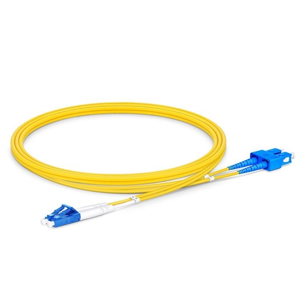
Every fiber optic patch cable has a rated attenuation and bandwidth. For example, OM1 is rated at 200 MHz·km at 850 nm and is intended for use in legacy applications. The higher OM ratings provide more speed and distance. Attenuation should remain within acceptable limits for reliable transmission. Executive Summary: Choosing the right fiber patch cable is one of the most consequential decisions in network infrastructure planning. The wrong choice — whether it's an underperforming multimode grade or an unnecessarily expensive singlemode run — can either cripple your network's reliability or. Fiber optic patch cords are key components for efficient, low-loss optical signal transmission between devices and fiber optic cabling links. One or both ends of the patch cord are equipped with standardized fiber optic connectors, and common interfaces include LC, SC, FC, ST, etc. They are manufactured and tested in compliance with TIA 604 (FOCIS), IEC 61754 and YD/T industry standards. OM1, OM2, OM3, OM4, OM5 or OS2 fiber types are available to meet the demand of. Fiber optic patch cables are ideal for supporting high speed telecommunication network fiber applications. They are lengths of optical fiber terminated with connectors on both ends. Their job is to connect two optical devices, like switches, routers, or optical transceivers that communicate.
[PDF]

Will fiber optic cables replace coaxial cables entirely? The short answer is: not entirely. In this article, we'll help you understand where each. Fiber optic cables and coaxial cables have something in common; both of them can provide homes and businesses with tv, phone, and Internet service. Cables. Optical fiber can carry analog RF signals from antenna to receiver with far less loss than coaxial cables. It's not unusual in engineering to find solutions to long-standing problems leveraging apparently unrelated technologies. But these signals have a fatal flaw: when transmitted through traditional copper coaxial cables, they degrade and distort rapidly over distance. It's like shouting into a long metal pipe—the sound that comes out the other. Seamless Radio Frequency Signal Transmission over Optical Networks RF over Fiber (RFoF) technology enables the transmission of radio frequency (RF) signals over optical fiber instead of traditional coaxial cables. This method combines the advantages of fiber optics—such as low signal attenuation.
[PDF]