You are looking at $0. The price swing usually depends on the fiber count (e., 12-core vs 96-core) and brand. Generic glass is cheap; premium glass (like Corning) costs more but guarantees lower attenuation. You are looking at $0. It is composed of 6 multimode fibers (50 micron core) inside a water blocking Aramid yarn wrapped in a black PVC outer jacket. Commercial building installations with 100-200 network drops generally range from $15,000 to $30,000. Single-mode fiber costs less per foot than multimode fiber, but it requires more. The unit cost of fiber optic cables can vary from $0. Here's a general pricing reference: Cable TypePrice Range (USD/meter)Simplex / Duplex Indoor Cable$0. 30Single-mode Outdoor Cable$0. 50Multimode (OM1/OM2/OM3)$0. 10 –. The price of fiber optic cabling depends on cable type, length, installation method, and surrounding materials. Typical costs hinge on fiber count, indoor versus outdoor use, and whether trenching, splicing, or termination is required.
[PDF]
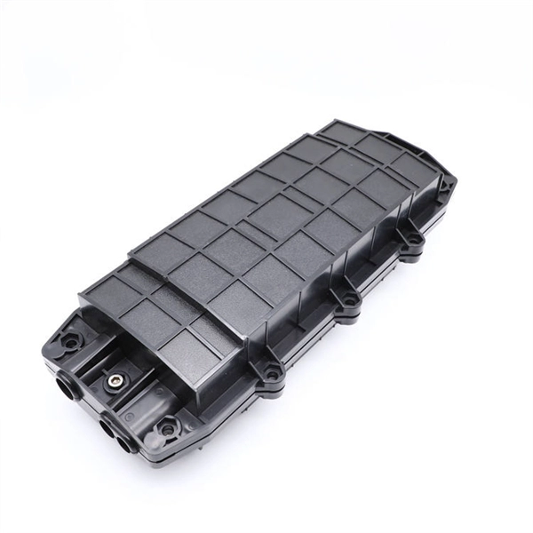
What does it take to make an effective explosion-proof junction box or cabinet? An incredible mechanical engineering design is what you need. Design for such enclosures and storage boxes differ with each m.
[PDF]

A 1U server rack measures exactly 1. 45 mm) in height and fits standard 19-inch racks. For example, a typical full-size rack cage is 42U high, while equipment is typically 1U, 2U, 3U, or 4U high. The rack unit size is based on a standard rack specification as defined in EIA -310. The Eurocard specifies a standard rack unit as the unit of height; it also defines a similar unit. U (rack unit, RU) is a unit of equipment height in a 19" rack. Important: U describes height only, but a server's real "capabilities" are also determined by chassis depth, internal layout, airflow, rails, power, and expansion (PCIe/risers, NVMe. Originally defined by the EIA-310 standard, the rack specifies a front panel width of 19 inches (482. 6 mm), allowing different hardware from various manufacturers to fit in the same enclosure. The unit calculator below can convert rack U's into cm, inches and feet. You'll get the precise, standardized dimensions of a 1U server rack unit — including height (1. 45 mm), width (19″ / 48. This three hole grouping is known as a rack unit (RU) or “U”.
[PDF]

Bury cables from 12-36 inches (or 30-90 cm) deep. Where plant life, sidewalks, and other utilities already disrupt earth, it's safer to bury at as little as 24 inches or 60 cm, using protective conduits to limit the likelihood of damaged cables by inexperienced maintenance or. Bury cables from 12-36 inches (or 30-90 cm) deep. However, simply hitting this depth isn't enough to guarantee your network survives. Factors like the. Requirements vary based on location, cable type, and local regulations, with depths typically ranging from 18 to 48 inches. Residential areas require depths between 24 and 36 inches for most installations. This protects cables from landscaping activities and minor excavation work. This. The question of how deep to bury fiber optic cable has no single answer, as the required depth changes significantly based on location, environment, and specific application. Industry standards and regulations, such as those often referenced in the National Electrical Code (NEC), establish a. Fiber optic cables are typically buried between 12 and 36 inches (30–90 cm), depending on installation environment, soil conditions, and load requirements. In high-load areas such as roads or backbone routes, burial depth can reach 48 inches (120 cm) or more. This guide provides a comprehensive overview of industry.
[PDF]

The FC/PC (Physical Contact) and FC/APC (Angled Physical Contact) fiber optic connectors are standardized under TIA EIA/TIA-604-4 and IEC 61754-13. ABSTRACT: This standard describes the point-to-point physical interface portions of Fibre Channel serial electrical and optical link variants that support the higher level Fibre Channel protocols includ-ing FC-FS, HIPPI, IPI, SCSI and others. This standard is recommended for new implementations but. Fiber connector types LC, SC, FC, ST, MTP, and MPO are widely used in past and present. What are the differences between them? Who is the most popular one? Find the answer in the article. What is a Fiber Connector? The optical fiber connector is a kind of detachable passive optical component used. An optical fiber connector is a device used to link optical fibers, facilitating the efficient transmission of light signals. An optical fiber connector enables quicker connection and disconnection than splicing. Unlike fiber splicing, which is permanent, connectors allow for easy connection and disconnection of cables, making them ideal for maintenance and flexibility in. Understanding fiber connector types—SC/APC, SC/PC, LC/UPC, LC/APC, ST/PC, FC/PC, and FC/APC—is essential for selecting the right interface for your application. Each type varies by shape, polish (APC, PC, or UPC), and return loss performance, which affect PC, UPC, and APC Polish Styles: What's the.
[PDF]
Designed by engineering firm PJ Ford Engineers, 25 Oldcastle Infrastructure CELL BLOCKS were manufactured to create the 35-foot by 35-foot foundation for the major telecom carrier's wireless cell tower, mi.
[PDF]
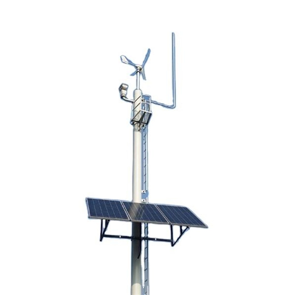
6Wresearch actively monitors the Nauru Telecom Towers and Allied Services Market and publishes its comprehensive annual report, highlighting emerging trends, growth drivers, revenue analysis, and forecast outlook. Welcome to Nauru Fibre Cable Corporation (NFCC), your gateway to reliable, high-speed internet and telecommunication services. Our insights help. The Department of ICT is governed by the Communications and Broadcasting Act 2018. The Department focuses on providing a reliable and resilient telecommunications infrastructure for all government departments and offices, schools and health clinics. Established in 2019, the company focuses on the design, construction, and management of telecom towers. Tawal operates a substantial portfolio of over 16,000 towers across the Kingdom, making it the first TowerCo.
[PDF]

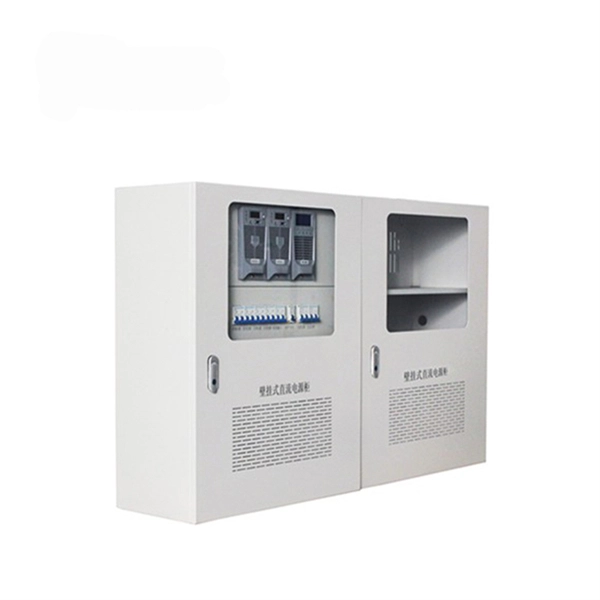
This AutoCAD DWG file includes a complete Single Line Diagram (SLD) of a Distribution Board, showing circuit breakers, wiring connections, and load distribution for lighting, power, and mechanical systems. An electrical panel box, also known as a breaker box or a distribution board, is a crucial component of any electrical system. It serves as a central hub for distributing electricity throughout a building, ensuring that power is delivered safely and efficiently to all the required locations. Whether you're an electrician or a DIY enthusiast, this guide will help you understand the basics of home electrical distribution. What is Distribution Board? Distribution board. Welcome to our channel @Electricalgenius In this video, we'll take you through a detailed step-by-step guide on wiring a home distribution DB (Distribution Board) box. A distribution board (also known as a service panel or breaker box) is a centralized collection of circuit breakers, fuses, and/or relays used to control and protect the wiring in a home. The diagram. To understand how a breaker box works, it is helpful to have a wiring diagram that shows the connections between the various components. At the heart of a breaker box is the main breaker, which controls the flow of electricity from the utility into the building. This breaker is connected to a.
[PDF]

In this video, we'll show you how to connect an energy meter to a distribution board (DB) safely and efficiently. A residential electric meter box wiring diagram illustrates the connection between the utility service drop and the main breaker panel. It shows the hot wire entering the meter lugs, the neutral wire connecting to the neutral bus bar, and the essential ground wire linkage to ensure system safety. energy meter connection with distribution box How to Connect an Energy Meter to Your Distribution Box Easily Steps to Properly Connect Your Energy Meter to a Distribution Box. This prevents arc faults and ensures safety when modifying or inspecting current paths. Inside the service housing, line conductors from the utility feed typically enter through the. The wiring that links the utility company's service point to a home's electrical distribution system is the main service connection. This “meter to panel” wiring establishes the pathway for all incoming electrical power from the grid to the home. Whether you're an electrician or a DIY enthusiast, this guide will help you understand the basics of home electrical distribution. What is Distribution Board? Distribution board.
[PDF]
An optical power meter (OPM) is a device used to measure the power in an signal. The term usually refers to a device for testing average power in systems. Other general purpose light power measuring devices are usually called,, power meters (can be sensors or ), or lux meters. A typical optical power meter consists of a , measuring and display. The sens.
[PDF]

In this video, we'll show you how to connect an energy meter to a distribution board (DB) safely and efficiently. energy meter connection with distribution box How to Connect an Energy Meter to Your Distribution Box Easily Steps to Properly Connect Your Energy Meter to a Distribution Box. Then I fix the box securely, route and terminate cables neatly, seal against weather, label clearly, and verify all connections before the utility energizes the service. I. Step-by-step guide to installing an electric meter box. Learn safety tips, wiring steps, troubleshooting, and when to call a pro. An electric meter box measures how much electricity your home uses. It helps the utility company give you the right bill. Installing an electric meter box might seem like a job for professionals only—but with the right knowledge, it's a task many homeowners. When your newly constructed or renovated home is ready for electric service, the power company will have to install an electric meter to monitor your electricity usage. The meter belongs to the power company, and it is responsible for installing it, but the electric meter box that contains it (also. Always begin with disconnecting the main supply before accessing any enclosure containing distribution components. This prevents arc faults and ensures safety when modifying or inspecting current paths.
[PDF]
Basic 300mm galvanized steel perforated trays can be found in the range of $1. 00 per meter, especially in bulk. Understanding the cable tray installation cost per meter is essential for effective budget planning. Costs vary based on tray material (steel, aluminum, or fiberglass), size, design (ladder or solid bottom), and installation complexity. Additional elements like supports, connectors, and brackets. Cable tray pricing depends on materials, coatings, size, supplier margins, and order quantity —plus hidden costs like shipping and installation. This guide breaks down everything buyers need to know, from price trends to cost-saving tips. The average cable tray price per meter ranges from $2 to. The majority of individuals will consider the cost of the components. But the actual price is the cash outlay to the workers to assemble the parts. Cable trays will tend to be significantly less expensive to use in 2026 than metal pipes due to their faster installation. 2 Why is Conduit So. Prices vary based on the size and load rating of the tray. For example: A standard 100mm wide GRP cable tray might cost around $15 per meter. Manufacturer and Brand Reputable brands often charge. The price for a 300mm width cable tray depends heavily on its type and material. We offer complete kits to provide you with cable tray ready to install under new or existing raised floors based on the unique requirements at your facility.
[PDF]
3‑E “Optical Fiber Cabling and Components Standard” was developed by the TIA TR‑42. 11 Optical Fiber Systems Subcommittee and published in September, 2022. Fiber optic patch cables are ideal for supporting high speed telecommunication network fiber applications. They are manufactured and tested in compliance with TIA 604 (FOCIS), IEC 61754 and YD/T industry standards. OM1, OM2, OM3, OM4, OM5 or OS2 fiber types are available to meet the demand of. Leviton fiber optic patch cords meet or exceed industry standards to make sure you get the performance you expect. They are available in multimode (OM1, OM3, OM4, OM5) and single-mode (OS2) fiber types, with a range of SC, ST and LC connectors. These standards are very important. They make sure patch cords work well, are safe, and can connect with other equipment. The high-quality fiber optic. ANSI/TIA‑568.
[PDF]