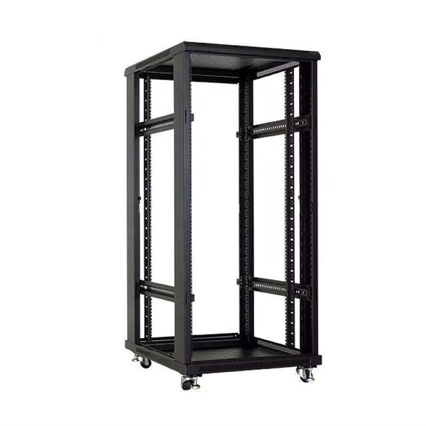
Run a ground wire from your metal patch panel rack to the grounding bar, use grounding lugs on the rack. Probably not necessary, but use Noalox between the lug and the rack. Remove paint if you want to go all in. Install and ground coax grounding blocks for your antenna. A Cat6 shielded patch panel is a modular component that connects and organizes multiple Ethernet cables in a central location. Unlike unshielded panels, shielded patch panels feature a conductive metal body and a grounding terminal to block EMI and maintain network integrity. GYA's shielded patch. A patch panel is a hardware device used to organize and manage network cable connections, helping to keep network wiring neat and efficient. Based on the shielding type, Cat6 copper patch panels are categorized into two types: shielded and unshielded. The rack itself is then bonded to the Secondary Busbar (SBB) of the telecommunications room. This. Correct STP grounding turns shielding into real EMI protection. This guide shows how to maintain drain‑wire continuity, bond safely at the equipment side, avoid ground loops, and validate results with simple tests. Cabling is cat5e UTP for data and phone. Coax is RG6 with 2 seperate runs, one for commercial tv provider, other for an attic mounted antenna that I'd like to eventually move to the roof. Is there a requirement (USA NEC) to.
[PDF]

The easiest way is to use the $3 "spec-grade" receptacles which come in a box instead of loose in a bin. If it's just black and white wires with a cloth or plastic covering and no ground wire you'd need a retroit grounding wire to have grounded outlets. A clearer picture of the cable entering will help. Can you post photos that show clearly where the cables enter the box at, please? @Traveler No!. The process of wiring a small breaker box, often called a subpanel, is a common task when adding power to a detached structure like a shed, garage, or a major home addition. These smaller distribution centers are designed to take power from a larger main service panel and distribute it locally to. How do I wire a mini circuit breaker distribution box that doesn't have bus bars? I have a circuit going to my shed from my house and I want to have two separate breakers inside the shed (one for outlets, one for other stuff) so I bought this from amazon (Amazon. com: 2 Way Distribution Box Circuit. In this video, we'll walk you through the process of wiring a home distribution box with a detailed connection diagram. more Welcome to our channel! In this video. Connecting a distribution box involves several steps to ensure proper electrical flow. But first, the rules: Turn off the power when working with electricity. Make sure the power's off using a non-contact voltage tester or multimeter. One final tip: Get into the habit of making connections in this.
[PDF]
The applicable subheading for the fiber optic panel/chassis and fiber optic patch tray, will be 9403. 8040, Harmonized Tariff Schedule of the United States (HTSUS), which provides for “Other furniture and parts thereof: Parts: Other: Other; Of metal. ” The rate of duty will be free. Item 1, part number LCXE-M1RU-BLK, is described as a fiber optic chassis with the capabilities of holding twelve fiber optic cables. The panel is produced from cold rolled. The merchandise is fiber optic patch panels that provide a consolidated point of demarcation for optical terminations, connections and cross connections within a passive, fiber optic network. They are designed to be mounted onto a wall or rack. All fiber optic patch panels will consist of the. Find verified buyers and sellers of Fiber Optic Patch Panel in 180+ countries along with their valid phone numbers and email ids. The top 3 Buyer countries for HS Code 851770 are “ PHILIPPINES ”, “ INDIA ”, “ PAKISTAN ”,. com if you have any questions or special project needs. The panel is produced from cold rolled. In the United States, customs duties imposed on imports from Asian countries have increased costs for Internet service providers and telecommunications companies, in many cases delaying infrastructure expansion and maintenance projects. In Latin America, several countries have adopted tariff.
[PDF]
A 24-port patch panel is a networking device that allows for the organization and management of incoming and outgoing network connections. It acts as an interface between different devices such as computers, switches, and routers, allowing for easy connectivity and communication. This guide explains how to use a 24-port patch panel to manage copper and fiber cabling in a small LAN, how to choose between different patch panel types, how to design your cabinet layout, and why a patch panel is still irreplaceable in 2026. What is a Patch Panel and Why it Matters in 2026? A. Choosing a 24-port patch panel is crucial for efficiency. Learn how it enhances network capabilities. Typically, patch panels are available in a huge number of port densities from 12. In this article, we will define what a patch panel 24 port is, explain its purpose, and discuss why it is a crucial component in organising network cables. A patch panel 24 port is a device used in network cabling to connect and organise multiple network cables in one central location. It is a. Choose a 24-port patch panel when you care about clean labeling, comfortable “finger room,” and fast moves/adds/changes—especially if technicians touch the rack often and you want straightforward port-to-port mapping (Panel 01–24 ↔ Switch 01–24). Choose based on port density, cabinet space.
[PDF]
The following figure shows a typical breaker box panel for 120V and 240V circuits. There are three wires entering the main panel from the energy meter viz: 1. Hot 1 or Line 1 = Black Color 2. Hot 2 or Line.
[PDF]

Have all of our in-stock product information and specifications right at your fingertips in digital PDF format. is a world class manufacturer of electronic wire and cable, both copper and fiber optic cable. Because of NATIONAL's service attributes and extensive cable manufacturing abilities, we offer a unique set of brand attributes: personalized service and product selection. You can get just about any. DOWNLOAD the Complete Catalog (PDF format 3. 9 MB) Download part numbers, descriptions and specifications of National Wire in-stock products by specific category or download the entire catalog. Heavy-Duty Flexible PVC Insulation – Crack-resistant and built for long-term durability. Versatile Use – Perfect for automotive, solar wiring, LED lighting, home projects, and RV systems. Guaranteed for. Fill out the form with your project details, and we'll help you every step of the way. Feedback! Don't miss out on anything, subscribe to our Newsletter! NNC © Copyright 2009 - 2026. Forgot your password?. Important! LANshack offers premium fiber optic cable & copper wire assemblies. We have all the components to optimize & install your network!. welcome to taobao purchase national standard soft copper wire 25 square millimeters 16 square millimeters copper core cable high-volume building welding machine welding wire welding machine welding machine welding soft copper wire.
[PDF]
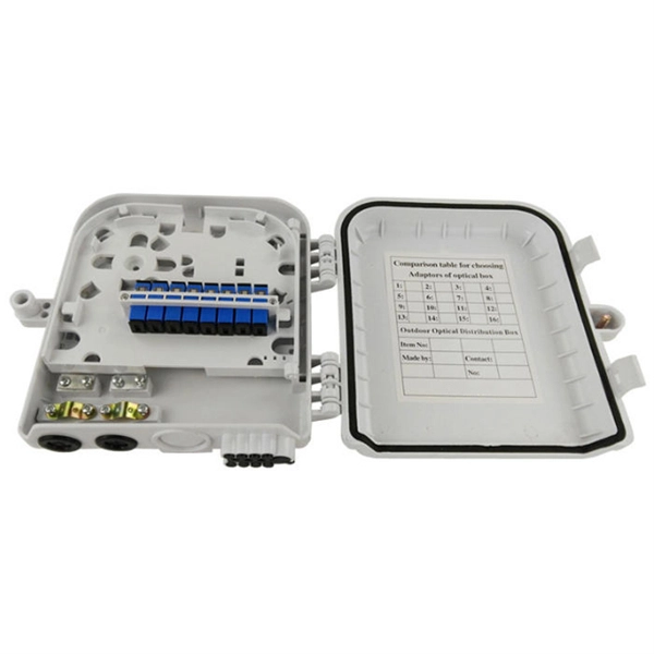
Dual door fiber enclosures provide our highest level of distribution panel security. They give you the option to separately lock the network and distribution doors for more control over panel access. The second doo.
[PDF]
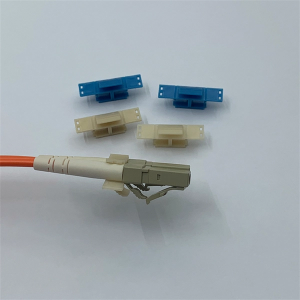
Designed to provide a clean, secure, and accessible termination point for indoor fiber connections, these outlets ensure optimal signal quality and minimal interference in residential and commercial environments. As fiber-to-the-home (FTTH) and fiber broadband continue to replace traditional copper infrastructure, the Fiber Optic Socket Wall Outlet has become an essential component of modern optical networks. These outlets act as the key connection point between your fiber optic cables and the devices that require fast, stable internet. A fiber wall socket (also called an optical termination outlet or FTTH outlet) is the critical endpoint where your home's fiber optic cable connects to the Optical Network Terminal (ONT). It ensures a clean, stable interface between the ISP's fiber network and your router—impacting speed, latency. These outlets, also known as fiber wall sockets or fiber optic outlets, play a crucial role in facilitating the transmission of data over long distances at incredible speeds. Splice holder is included. The optical trunk outlet is designed for installation in Schneider/Thorsman 80mm ducts. Trunk outlet for fiber optics delivered with adapter and pigtails.
[PDF]
If an EGC cable is installed in or on a cable tray, it should be bonded to each or alternate cable tray sections via grounding clamps (this is not required by the NEC® but it is a desirable practice). Cable tray may be used as the Equipment Grounding Conductor (EGC) in any installation where qualified persons will service the installed cable tray system. There is no restriction as to where the cable tray system is installed. The metal in cable trays may be used as the EGC as per the limitations. Cable tray grounding wire is the safety connection that links your electrical system's cable tray to the ground. This provides a safe path for any stray electrical currents to flow safely into the earth, avoiding damage to your equipment and reducing the risk of electric shocks. Grounding points and conductor locations must be determined. The design must comply with relevant regulations and standards.
[PDF]

This section applies to grounding of transmission and distribution lines and equipment for the purpose of protecting employees. Note to paragraph (a): This section covers. Correct grounding of services depends upon understanding the definition and role of the grounded conductor. The neutral conductor is typically the grounded conductor connected to the system's neutral point, carrying current under normal operation. Grounding electrode conductors must be connected at. Learn the grounding and bonding rules when powering two or more buildings or structures in the same area with a single service. To catch up on Lorenzo Mari's series on National Electrical Code 2023 Basics: Grounding and Bonding, follow these links: NEC's Section 250. Bonding is connecting things together with a conductive path to establish electrical continuity. Both are foundational safety concepts in the NEC, and. NFPA 70: National Electrical Code Article 250 covers the minimum requirements for grounding and bonding and, although the NEC lists requirements to abide by, it should not be taken as a design manual. Some terms and requirements discussed may be true for the European standards, however, the intent.
[PDF]

The process involves a combination of national infrastructure, local engineering, and property-level setup. In this guide, we'll break down the fiber installation process from start to finish and explain key components such as fiber cabinets, flower pods, ducting, and ONT. Our fiber optic installation process covers everything from planning and preparation to termination and testing. But how does it work? Keep reading to find out. What Is Fiber Optic. This fiber optic installation method statement covers the termination of fiber optic cables with patch panel, network distribution cabinet NDC and door junction box but can be applicable for any kind of network installations. Roles and Responsibilities: The electrical manager shall be responsible. Setting up a fiber optic network requires careful planning and execution. This guide provides a step-by-step overview of the installation process, ensuring a smooth transition from traditional cabling systems. Introduction Installing a fiber optic network can seem daunting, but with the right. This beginner-friendly guide will walk you through the step-by-step process of fiber optic cable installation for each method, highlighting best practices, tools, and considerations. Unlike traditional copper wiring, fiber optics installation provides superior bandwidth, faster speeds, and resistance to electromagnetic interference.
[PDF]

In this article, you will learn the step-by-step process of testing your solar panels using a multimeter. We will cover the essential tools you need, the specific measurements to take, and how to interpret the results. A $15 multimeter and 5 minutes of testing can diagnose most solar panel problems. Measure Voc (open circuit voltage) — if it reads 0V, the panel or wiring is dead. If it reads 60–80 % of rated, a bypass diode has failed. By the end of this guide, you will be equipped with the knowledge to diagnose. Learning how to test solar panel with multimeter is useful for homeowners, technicians, farmers, and anyone using solar energy systems. A digital multimeter allows you to check voltage, current, continuity, and resistance. Fluke recommends using the Fluke 117 Electrician's Multimeter or Fluke 283 FC CAT III 1500 V Digital Multimeter to test solar modules. Here's how a technician tests solar modules with a multimeter:. A multimeter is an indispensable tool for anyone working with solar panels, allowing for accurate measurements and diagnostics. It empowers users to assess the performance, identify faults, and ensure optimal energy production. Perfect for DIY solar builders, RV owners, o. more Audio tracks for some languages.
[PDF]
Photovoltaic modules, or solar modules, are devices that gather energy from the sun and convert it into electrical power through the use of semiconductor-based cells. A photovoltaic module contains numerous photovoltaic cells that operate in tandem to produce electricity. A single PV device is known as a cell. An individual PV cell is usually small, typically producing about 1 or 2 watts of power. These cells are made of different. Photovoltaics (PV) is the conversion of light into electricity using semiconducting materials that exhibit the photovoltaic effect, a phenomenon studied in physics, photochemistry, and electrochemistry. Here is a description of their main features and of Enel Green Power's innovative solution. A semiconductor.
[PDF]