
This paper explores the latest trends in the cable tray manufacturing industry, focusing on technological advancements and sustainable practices. It covers the integration of IoT for smart monitoring, the use of innovative materials for enhanced durability, and modern. In 2025, the landscape of cable management has evolved significantly, with cable trays playing a pivotal role in supporting the complex wiring systems of modern infrastructure. The Global Cable Trays and Ladders Market plays a pivotal role in modern infrastructure, enabling secure and efficient routing of power and communication cables in industrial, commercial, and residential environments. These systems provide structural support, organization, and safety in electrical. The cable tray market is projected to grow from USD 4. 3 billion in 2025 to USD 5. Metal will dominate with a 63. 4% market share, while ladder cable trays will lead the product type segment with a 42. This global Cable Tray Systems market research report provides a comprehensive overview by conducting both.
[PDF]

More specifically, these systems keep tabs on voltage, current, and temperature limits and control the disconnect relay. This allows them to disconnect themselves from the external application in case of malfunction. From a drop of rain to the shining sea, an energy storage system is like the earth's bodies of water (hear us out). In a battery energy storage system (BESS), the energy in the battery cells is like raindrops that combine to form a brook. Made of the combined energy from cells, these brooks combine. Battery energy storage systems (BESSs) investment is expected to grow to $103 billion by 2030. ) Battery systems aren't just designed to serve as local power backups, such as the systems used to power critical facilities (including hospitals and data centers) when the normal. When a 300 MWh battery energy storage system (BESS) in Arizona tripped offline during July's heatwave, operators discovered voltage fluctuations had overwhelmed its protection relays. Could your facility withstand such stress? As global BESS installations surge—projected to reach 1. Protection is necessary when energy and voltages combine from the modules, as well as from the battery racks. Fuses are an efficient. The electrical integration design of a Battery Energy Storage System (BESS) is based on the application scenario and includes various aspects such as DC, high/low voltage distribution, control power distribution, grounding, lightning protection, and safety standards.
[PDF]
Discover AZE's advanced All-in-One Energy Storage Cabinet and BESS Cabinets – modular, scalable, and safe energy storage solutions. Featuring lithium-ion batteries, integrated thermal management, and smart BMS technology, these cabinets are perfect for grid-tied, off-grid, and. rgy storage technology has become a key pillar in building new-generation power systems. It is being widely deployed across grid peak-shaving, me retardancy, non-toxicity, RoHS/R foam, addressing the dual needs of noise and thermal control in energy storage systems. This solution has been. Relying on its cutting-edge clean power conversion technology, industry-leading battery technologyand grid forming technology, Sungrow focuses on integrated energy storage systemsolutions. The core components of these systems include PCS, lithium-ion batteries and energy management systems. But hold onto your solar panels, because this Middle Eastern gem is quietly becoming a laboratory for energy storage innovation. From government officials sweating over. Energy experts have lauded the Cabinet's recent approval of a grid-scale battery energy storage system (BESS) for the National Electric Power Company's transmission. Hybrid Solar-Geothermal Heat Pump Systems: Simulated for various Jordanian locations, these systems incorporate storage to optimize.
[PDF]

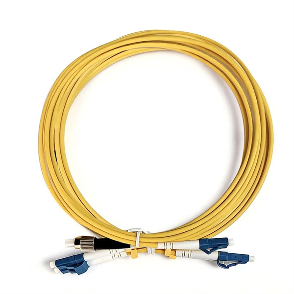
For a conventional optical module, we can easily judge the wavelength of the optical module from the color of the latch ring. For example, the black pull ring represents 850nm, and the blue pull ring represents 1310nm. Distinguish the wavelength by the color of the pull ring of the optical module In order to distinguish their own optical modules, different manufacturers can distinguish them by their wavelength, transmission distance, packaging, etc. In the complex infrastructure of data centers, optical modules are critical components that. The utility model discloses a pull ring device suitable for an optical module, and belongs to the technical field of optical communication. This article provides a professional guide on transceiver pull tab color codes by wavelength—spanning SFP, SFP+, CWDM, and BiDi modules—and introduces how LINK-PP standardizes. These modules convert electrical signals into optical signals, which transmit data over distances of fiber optic cables with minimal power loss. The topic of specifications and physical traits is one aspect of this question; another often-overlooked detail is the color of the pull tab. This modest. The ControlLogix® Architecture provides a wide range from high-speed digital to process control. The ControlLogix which allows input information and output status to Rockwell Automation recognizes that some of the terms that are currently used in our industry and in this publication are not in.
[PDF]
Optical modules are essential components in modern communication networks, enabling high-speed data transmission over fiber optic cables. As the demand for faster and more reliable internet and data services grows, understanding these devices becomes increasingly important. Optical modules typically have an electrical interface on the side that connects to the inside of the system and an optical interface on the side that connects to the outside. That is, metal medium communication represented by coaxial cables and network cables is gradually being replaced by optical fiber media. Composition of Optical Modules The optical module, known as Optical Transceiver in. The optical module serves as a crucial component in optical fiber communication systems, operating at the physical layer, which is the lowest layer in the OSI model. Its primary function is to achieve optoelectronic conversion by converting electrical signals into optical signals and vice versa.
[PDF]

These core components of optical fiber communication system — transmitter, optical fiber, receiver, plus supporting elements like amplifiers and multiplexers — enable lightning-fast, interference-free communication over vast distances. Fiber optic communication refers to a method of transmitting data that utilizes light instead of electrical signals to send information through optical fibers. It works on the principle of total internal reflection, allowing light to move through the fiber with very little loss. The process kicks. In order to comprehend how fiber optic applications work, it is important to understand the components of a fiber optic link. Simplistically, there are four main components in a fiber optic link (Figure 1). These systems rely on three vital components working together – the communication channel, the optical transmitter, and the optical receiver. Optical fiber communication system 1. Encoder Encoder converts the analog information like voice, figures, objects etc into the binary data. Optical fibers are thin, flexible strands of glass or plastic that serve as the medium for transmitting light signals. Some exceptional characteristic features of this type of communication system like large bandwidth, smaller diameter, lightweight, long-distance signal.
[PDF]
Optical modules have a series of components inside, some of which have received attention from standards development organizations. In many cases, the baud rate of the optical interface does not equal the baud rate of the electrical interface. In these cases, a gearbox is used within the module to convert between the two rates. For example if the module supports 4 x 25 Gb/s electrical inputs and 2 wavelengths of 50 Gb/s optical inte.
[PDF]

It consists of an optical fiber and a lens, where the fiber guides the light and the lens collimates it. The primary purpose of a fiber collimator is to couple light efficiently from a fiber into free space or another optical component, ensuring minimal divergence and optimal. Fiber-optic collimators are used to launch the light from an optical fiber into a free space collimated beam with specified beam diameter or spot size. In essence, a simple collimation lens is all that is needed for this purpose. They are widely used in. To couple light both into and out of an optical fiber, it is essential to have a collimated light beam. To meet this demand, LASER COMPONENTS developed its own collimator systems. It typically consists of: Optical fiber section – single-mode fiber (SMF) is most common, but polarization-maintaining (PMF) or multimode fiber (MMF) can also be used. Miniature lens – such as a C-lens. Other fiber collimators have a mechanical interface to a fiber connector, e. of FC or SMA type; they are not for use with bare fibers. One can easily attach and remove such a collimator from a connectorized fiber. Commercially offered collimators may offer several directional adjustments, e. Our Polaris ® Kinematic Collimators offer high-quality.
[PDF]

