USB keyboards, mice, and I/O devices are the most common devices connected to a KVM switch. The classes of KVM switches discussed below are based on different types of core technologies, which vary in how the KVM switch handles USB I/O devices—including keyboards, mice, touchscreen displays, etc. (USB-HID = USB ) USB Hub Based KVM Also called an Enumerated KVM switch or USB switch selector, a connected/sh.
[PDF]
Engineers involved in the design, characterization and validation of Universal Serial Bus Revision 2.0 (USB 2.0) devices face pressure to speed new products to market. Tools are available to help them quickl.
[PDF]
The Patch and Splice Combo Patch Panel is designed to allow both the patching and splicing of fiber optic cable all in one unit; these particular units have fiber termination panels in the upper slide out shelf and splice trays in the lower shelf. NG4access ® Cabled Modules available in all module sizes and fiber counts up to 864 fibers NG4access ® Splice Tray Four sizes of interchangeable Propel fiber pass-through adapter packs provide the breadth of capabilities for virtually any configuration. Four sizes of interchangeable Propel fiber. Cisco is introducing a family of fiber management solutions with a debut of SMF and MMF patch panels. The panels will enable Cisco's customers to facilitate breakout connectivity agnostic of the data rate. The Cisco® solution of panel and cable assemblies offers versatile solution for any breakout. Our fiber patch panel offers options for flexible cable management and seamless integration with various cassettes and fiber optic accessories. Allowing full front access for network. Foss FP-series front patch panels are made with the highest accuracy for precise fitting. All panels are tested according to both our own quality measures and international standards before they are sent to customers. Similarly, the ABS High Density Shelves bring a new level of access, convenience, and security to its Fiber Splice Shelf, enabling quick and easy fiber splicing and connectivity for rack mount applications.
[PDF]

Function: Analog switches are designed to pass or isolate analog signals. They essentially route analog signals based on a control signal. Examples: The CD4066B (CMOS Quad Bilateral Switch) and the SN74HC4066 (quadruple bilateral analog switch) from Texas Instruments are popular. Solid-state analog switches and multiplexers have become an essential component in the design of electronic systems which require the ability to control and select a specified transmission path for an analog signal. These switches provide bidirectional connections when “on” and high impedance paths when “off. Analog inputs are used to measure changes in process through sensors, subsequently converting that signal to voltage or current and sending it to modules that measure this change to determine new setpoints. Many remote and local I/O systems can use discrete and analog input signals. What. In the example below, an RF input signal is added to a DAC output or switched to GND. Due to the high frequency of the RF signal, any switching transients of the switch would disturb the RF output signal, thus any. Texas Instruments offers a wide variety of switches and multiplexers supporting a variety of configuration, voltage, bandwidth, and package needs. This application note summarizes the key features and performance characteristics of our analog signal switches and application considerations for.
[PDF]
Modern fiber-optic communication systems generally include optical transmitters that convert electrical signals into optical signals, optical fiber cables to carry the signal, optical amplifiers, and optical receivers to convert the signal back into an electrical signal. The information transmitted is typically digital information generated by computers or telephone systems. Transmitters The most commo. OverviewFiber-optic communication is a form of for from one place to another by sending pulses of or through an. The light is a form of. First developed in the 1970s, fiber-optics have revolutionized the industry and have played a major role in the advent of the. Because of its advantages over electrical transmission, optical fiber. is used by telecommunications companies to transmit telephone signals, Internet communication and cable television signals. It is also used in other industries, including medical, defense, governmen.
[PDF]
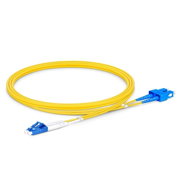
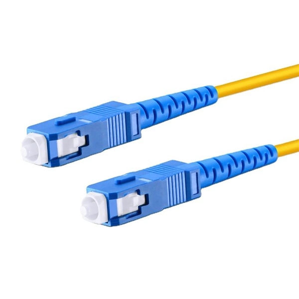
Splicing allows you to restore or expand fiber networks while maintaining signal integrity. When done right, splicing ensures minimal loss and long-lasting performance. This is where fiber optic cable splicing—the process of creating a permanent, high-performance join between two fiber ends—becomes critical. For network managers and technicians, a poor splice can lead to significant signal degradation, network downtime, and costly troubleshooting. At Turn-Key. To begin, the standard definition of splicing in optical fiber is joining two fiber optic cables together. The other, more common, method of joining fibers is called termination or connectorization. Splicing is most commonly used in the field but has application in cable assembly houses. Whether repairing a broken cable or extending a fiber run, fiber optic splicing ensures light signals travel. Whether you're installing new cables or repairing damaged ones, splicing techniques play a vital role in maintaining signal integrity. Choosing the right method affects performance, cost, and long-term durability. In this blog, we'll explore the main types of fiber optic splicing techniques, their. Joining two optical fibers at the right place so that light can be transmitted through them with minimal loss and reflection is known as splicing. Fiber optic splicing is done through two main methods. In fusion splicing, the ends of the fibers are welded together with heat. This guide will walk you.
[PDF]

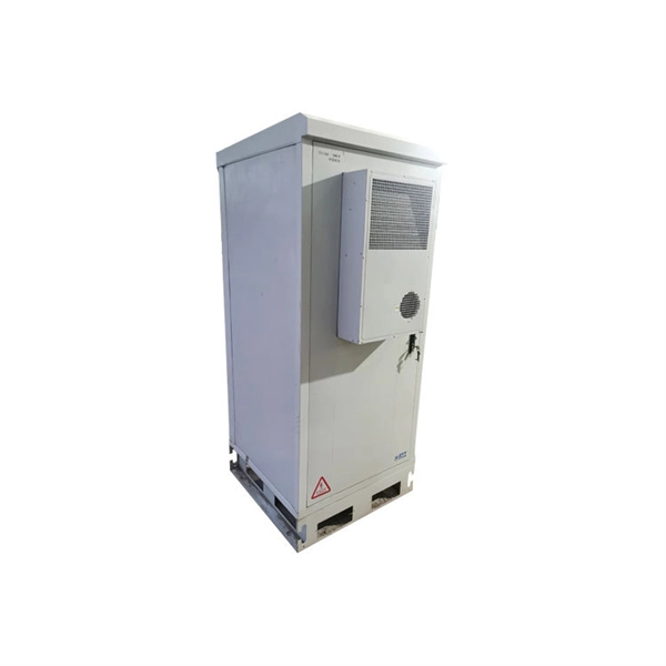
Cable trays are mechanical support systems that provide a rigid structural system for electrical cables, raceways, and insulated conductors used for electric power distribution, control, signal instrumentation, and communication. Cable trays are used as an alternative to open wiring or electrical conduit systems, and are commonly used for cable management in. maintain spacing or to keep cables in place when the tray is ect the minimum bend ra-dius for cables as they exit the bottom of the cable tray. Metal cable trays are made of galvanized steel, stainless steel, and. The modern world relies heavily on electrical and communication cables that must be managed and supported across vast distances in commercial and industrial settings. A cable tray is an organized support structure designed to secure and route these insulated electrical cables. It acts as a. For safe application, observe the following: WARNING To prevent from shock, short-circuits or damage, observe the following: • Be sure the power is disconnected before replacement (fuse exchange, etc. • Use this product in a properly maintained condition. (Replace or repair if the body. What is a cable tray? A cable tray is a metal or non-metal structure used to lay electrical cables and wires, serving to support, protect, and guide the cables. What is the role of a cable tray in electrical engineering? A cable tray allows for the neat and aesthetic arrangement of cables.
[PDF]

A differential encoder is often used for bit synchronization. The polarity of the differentially encoded signal can be inverted without having any effect on the decoded signal waveform. A photoelectric signal, output by a photoelectric receiver, may detrimentally change after the photoelectric encoder is used for a period of time or when the environment changes; this will directly affect the accuracy of the encoder and lead to fatal errors in the encoder. To maintain its high. The grating eddy-current of DGECE consists of a circular array of trapezoidal reflection conductors and 16 trapezoidal coils with a special structure to form a differential relationship, which are respectively located on the code plate and the readout plate designed by a printed circuit board. 2 Example showing decoding is the same. This encoder signal error means your A, B, or R channels aren't correctly inverted. Learn how to test your encoder, cabling, and signal integrity. In high-performance control systems using the Siemens SINAMICS drive family, the encoder feedback is crucial. This also changes the direction of the rotation of the constellation changes. In the past I have been told channels. But I have also read that a spectral inversion is equivalent indicate this may be true.
[PDF]