Buy Panduit LabelCore Fiber Optic Cable Identification System Self-Laminating Laser/Ink Jet Labels at SHI. See detailed specifications and benefit from expert support. Shop IT hardware and software products with SHI now!. Indoor & outdoor fiber cable high visibility markers, id labels, printers, warning signs & posts, cable id sleeves and more for fiber optic applications. Check each product page for other buying options. Need help? Explore write-on fiber optic cable tags with self-laminating protection. Keep your cables organized and clearly labeled with writable identification solutions. The Multilink cable markers utilize a simple and quick installation that allows the installer to simply wrap the marker around the selected cable without the need for special tools or adhesives. The UV stabilized body will not degrade in outside applications and a variety of colors allows easy. According to research conducted by industry experts that shows network failures cost businesses the equivalent of five thousand dollars per minute. If technicians aren't able to quickly recognize the correct cable, these minutes can add up quickly. The TIA/EIA-606-A standard has created a unified system that specifies a "common" method of labeling the complete telecommunication infrastructure. PANDUIT Labeling Software packages include all label formats for quick and.
[PDF]
Unlike traditional metal-style reels, MARS is a lightweight, modular system constructed of an impact modified polymer that is easily transported. It is ideal for applications where cable needs to be deployed and reeled in quickly and stored efficiently. OCC's Modular Advanced Reel System (MARS ®), the industry's first lightweight cable deployment reel system, is designed specifically for the demanding needs of harsh-environment fiber optic installations. The dual take-ups are designed to work independently from line controls, therefore providing an easy adaptation and a fast plug & play installation to any line.
[PDF]
This comprehensive guide will delve into the best practices for cable removal, the benefits of maintaining a clean cable environment, and step-by-step instructions to ensure the process is efficient and compliant with industry standards. Every new installation means an increased number of low voltage cables that are cut and left in ceilings, floors, and walls. From a tenant or building owner's point of view, removing abandoned cable has. Effective cable removal ensures safety, optimizes performance, and prepares the infrastructure for future upgrades. Before beginning any installation, safety. Fiber-optic cables are the backbone of modern connectivity—powering 5G networks, global internet backbones, and data center interconnections with near-light-speed data transmission. While these cables are engineered for durability (with some rated to last 25+ years), they are not invulnerable. Even. Here are 5 vital rules for staying safe when you're working on fiber optic cables. Know the standards that apply to your work Whether you're installing new fiber optic cables or troubleshooting and repairing an existing fiber network, a working knowledge of the regulations that apply to your. In outside plant fiber optic installations, the biggest cause of network failure is likely to be electronic problems or, if it's in the cable plant, what is usually called “backhoe fade” for buried cables and “target practice” for aerial cables, both of which are self-explanatory.
[PDF]

In this article, we will discuss the wiring diagram for a typical 6 terminal junction box, which is commonly used in residential and commercial buildings for a variety of applications. Learn how to wire a distribution box step by step! This video shows real on-site footage of electrical installation, demonstrating safe and standardized wiring methods used by professionals. Wiring Direction: Wiring between the main circuit breaker and each branch circuit breaker in the box generally. In this guide, we'll break down everything you need to know to install a distribution box correctly and confidently. Choose the right box based on environment (indoor/outdoor), load capacity, and durability. Check for proper IP/NEMA ratings and material quality. Ensure safe placement: install in. It is the policy of the Company to serve all its customers in an orderly manner and assist in securing a more beneficial use of electricity. The “Xcel Energy Standard for Electric Installation and Use” contains the requirements and uniform standards necessary to achieve this policy. Uniform. An electrical panel box, also known as a breaker box or a distribution board, is a crucial component of any electrical system. It serves as a central hub for distributing electricity throughout a building, ensuring that power is delivered safely and efficiently to all the required locations. The 6 terminal junction box wiring diagram provides a visual representation of how the various wires and.
[PDF]

In this video, we'll walk you through the process of wiring a home distribution box with a detailed connection diagram. Whether you're an electrician or a DIY enthusiast, this guide will help you understand the basics of home electrical distribution. more Welcome to our. Material preparation: Prepare the required circuit breakers, wires, wiring ties and other materials, and ensure that they meet the design drawings and installation requirements. Location determination: Determine the installation position of the circuit breaker according to the position of the. An electrical panel box, also known as a breaker box or a distribution board, is a crucial component of any electrical system. It serves as a central hub for distributing electricity throughout a building, ensuring that power is delivered safely and efficiently to all the required locations. What is Distribution Board? Distribution board. A distribution board (also known as a service panel or breaker box) is a centralized collection of circuit breakers, fuses, and/or relays used to control and protect the wiring in a home. The diagram of the distribution board's wiring shows exactly how each circuit is wired and connected.
[PDF]
The hot and cold aisles in the data center are part of an energy-efficient layout for server racksand other computing equipment. The goal of a hot/cold aisle configuration is to manage airflow in a way that c.
[PDF]

The block diagram in Figure 1 shows a very basic laser diode driver (or sometimes known as a laser diode power supply). Each symbol is defined in the table below. Laser diode drivers vary widely in feature set and. The KLD101 K-Cube ® Laser Diode Controller is a compact, versatile module designed to drive a wide range of semiconductor laser diodes and LEDs. It supports operating currents up to 230 mA, a compliance voltage up to 10 V at 50 mA (>7 V at 230 mA), and both constant current and constant power. I recently (10/2024) bought a Swiitol E24 PRO laser (I think it's identical to the Atomstack. ) that I want to use with an HP laptop with Windows 11. My problem is that I can't make contact with the diode laser with the laptop/Lightburn (GRBL)! I checked the following: All plugs and cables, laser is. A laser diode (LD, also injection laser diode or ILD or semiconductor laser or diode laser) is a semiconductor device similar to a light-emitting diode in which a diode pumped directly with electrical current can create lasing conditions at the diode's junction. : 3 Driven by voltage, the doped. Laser diodes (LD) are semiconductor devices that convert electrical energy into high-power optical energy. These devices are currently used in the fields of telecommunications and medicine and in industrial cutting and welding applications. These gadgets track down wide applications because of their proficiency and minimal size. This block diagram is a.
[PDF]

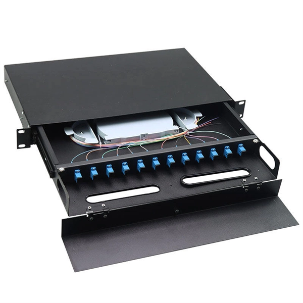
Connecting a fiber patch cord involves carefully inserting it into the appropriate adapter after ensuring the connectors are clean. The process may differ slightly depending on the type of connector. The core process involves two main stages: preparation and insertion. Planning helps you pick the right cord for your network. Be gentle when you handle the cord. Fibre patch cords last longer and are tougher than copper cables. They also protect better from interference. Look at the table below to compare:. Connecting a fiber optic patch panel may seem daunting at first, but if you follow the right steps, it's actually quite simple – and can even be done in just a few minutes. Preparation: Before. Fiber Optic Transceivers: For converting signals between optical and electrical form. Cleaver: For precisely cutting the fibers. Safety Equipment: Gloves. In today's high-performance networks, fiber optic patch cables are the lifelines that ensure smooth data flow across switches, servers, and routers. Even the most advanced optical transceivers can only perform at their peak when paired with properly installed, clean, and precisely managed fiber. Correct patch-cord installation is essential for maintaining low insertion loss, stable return loss, and long-term reliability in both indoor and outdoor fiber networks. Proper handling, routing, cleaning, bend-radius management, and connector alignment ensure that the optical link meets design.
[PDF]

This video provides a detailed walkthrough of designing and simulating an automatic light control system using Light-Dependent Resistor (LDR) and Triac in Proteus Software. Last updated on 13 August 2025 by Admin-Lavi Leave a Comment This article talks about Light Controlled Switch Circuit using IC LM311 and LDR. It simple and very useful and it feel light change near it. We find this circuit in many place like automatic light, street lamp and security system. Main. ABB's Control Room offering includes a comprehensive range of solutions designed to optimize the operator workspace for critical 24/7 processes across various industries. The project demonstrates how to create a smart lighting system that turns on/off automatically based. more This video. The Intro Screen changes as you play with it. It has a Play Area and a Control Area. A Construction Area creates a building space for components added from a Circuit Component Toolbox. Build and navigate your circuits there. If Voltmeters and Ammeters are out of the toolbox, you can take. Common sense schematics let you name a node "+5V" and know that the simulator will do the right thing automatically, keeping your schematics compact and elegant. This circuit activates or deactivates connected loads, such as LEDs or light bulbs, based on ambient light levels.
[PDF]

This video shows real on-site footage of electrical installation, demonstrating safe and standardized wiring methods used by professionals. more Learn how to wire a distribution box step by step! This video shows real on-site footage of. Understanding the wiring diagram of an electrical panel box is essential for electricians and homeowners alike, as it allows them to troubleshoot any electrical issues, carry out repairs, or make additions to the system. The electrical panel box wiring diagram provides a visual representation of. A distribution box is the heart of any electrical system. It takes the incoming power and safely distributes it to different circuits throughout your building. Whether in a home or an industrial facility, this box keeps your electrical setup organized, functional, and efficient. However, the key to. In this video, we'll walk you through the process of wiring a home distribution box with a detailed connection diagram. It has three categories: residential, commercial and industrial electrical distribution boxes, all of which play important roles in their respective electrical. It is responsible for distributing electricity throughout a building, ensuring that each circuit receives the proper amount of power. To understand how a breaker box works, it is helpful to have a wiring diagram that shows the connections between the various components. At the heart of a breaker.
[PDF]

Complete pv combiner box wiring diagram guide covering string connections, grounding methods, bonding requirements, and NEC-compliant installation procedures for solar systems. Most wiring diagrams supplied with commercial combiner boxes are simple, easy-to-understand. A clear wiring diagram helps installers understand the flow of current from each string to the main DC bus, making the system safer and easier to maintain. For systems with three or more DC strings, using a solar combiner box is recommended according to international PV safety standards such as IEC. This wiring diagram will guide you in understanding how to properly wire a PV combiner box. One of the key elements of a PV combiner box is the array of fuses or circuit breakers. These safety devices protect the solar panels from overcurrent and short circuits. Understanding proper wiring topology, conductor sizing methodology, and grounding. ing connections,fusing,and grounding. Following the diagram will help ensure the safety,efficiency,and long-term perform nce of your solar panel installat el off the outer shea h of the cable. Check if t is level. Check vertica deviation. Bandage exposed wire. Mea ure. This piece will address the components required for a DC PV combiner box, how to read its wiring diagram and provide a step-by-step tutorial on how to wire it safely and efficiently.
[PDF]

In this guide, you will find a chronological description of the fusion splicing process, the principal technical standards, and answers to the real-life questions network engineers and procurement teams may have. In this guide, we cover the basics of fiber optic splicing, how to perform splicing using two different methods, and finally some best practices to perform good fiber splicing. What is Fiber Optic Splicing and Why is it Needed? – #1. Use and Maintain Your. This Geoschematics drawing remains easy to read despite containing more than 2000 fibers and 500 splices. Splice Diagrams or Matrices capture an electric or optical network inside a location – documenting cables, ported equipment, and connections. Splices are fiber-to-fiber, port-to-fiber and. This guide will walk you through the complete process of fiber optic splicing—covering each step in detail so you can deliver a clean, professional splice every time. Before jumping into the physical steps, it's important to understand the two primary methods of fiber splicing: fusion splicing and. Page 1 The FOSC 450 fiber optic splice closures use compressed-gel cable seals to environmentally seal fiber cable splice points. FOSC 450-ab-c-dd-e-fgh The maximum single splice capacity of the FOSC 450 B6 closure is a = Closure size 144 with 24 splices stored on six trays. Therefore, we will also touch on cost factors, risk management, and best practices in.
[PDF]

Abstract:The design, installation, and protection of wire and cable systems in substations are covered in this guide, with the objective of minimizing cable failures and their consequences. In modern electrical systems, cable distribution boxes (also known as electrical distribution boxes or distribution boxes) play a crucial role as the key hub for managing, distributing, and protecting circuits. Whether it is residential buildings, commercial facilities or industrial sites, the. The power demanded in electricity systems also determines the cable cross-section and properties as well as the current to be transferred. In case of high power use, to meet the demand of currentAnd in order for the current to be carried at the demanded high powers to be met, the method of parallel. A distribution box is the heart of any electrical system. It takes the incoming power and safely distributes it to different circuits throughout your building. Whether in a home or an industrial facility, this box keeps your electrical setup organized, functional, and efficient. However, the key to. Distribution Board or DB is an electricity supply system or a common enclosure that distributes the electrical power feed into subcircuits. Armored Cable (Type AC). Armored cable is an assembly of insulated conductors, 14 AWG through 1 WG, wrapped with waxed paper. The conductors are contained within a fl exible spiral metal (steel or al minum) sheath that the edges.
[PDF]