The system in this example contains the following elements: 1. 2 Pseudo-random Bit Stream (PRBS) block 2. 2 NRZ Pulse Generator (NRZ) 3. 1 CW Laser (CWL) 4. 3 1x2 Fork (FORK) 5. 2 Electrical Not Gate (N.
[PDF]

Filter your results below. The 400G OSFP SR8 optical module supports speeds up to 425Gbps, short-range distance reaching up to 100m over 16 parallel multimode fiber (MMF) OM4. OSFP-400G-SR8 has an MTP/MPO-16 connector. 400G SR8 is designed based on PAM4 (Pulse Amplitude Modulation 4-level) modulation technology, DSP (Digital. MaxLinear's highly integrated PAM4 DSPs offer superior link-margin performance and low power to enable 100G, 400G, 800G, and 1. 6T optical interconnects inside the data center. NADDOD OSFP-400G-SR4 optical transceiver is a four-channel, parallel, pluggable fiber-optic OSFP with built-in Broadcom DSP and Broadcom VCSEL, designed for 400G Ethernet applications. It integrates four transmit and four receive lanes, each operating at 53. 125 GBd, delivering an aggregate. Support 100GBASE per lane in multimode fiber. Fibres: 8 fibres (ribbon patchord). Hot-pluggable OSFP Type form factor. Data rate up to 425Gbps (4x 10⁶. Connector: MPO-16/APC. Max reach: 100m, over multimode OM4 (MMF) fibre. This high-performance module is optimized for short-range data communication and interconnect applications, delivering exceptional speed and reliability. It integrates. The Marvell® PAM4 optical DSP portfolio, including Spica™ and Nova™ DSPs, addresses the critical the need for high-bandwidth optical interconnects to power AI infrastructure. Marvell leads the pluggable module ecosystem with low-power, high-performance silicon for AI, cloud, enterprise and 5G.
[PDF]
Splicing allows you to restore or expand fiber networks while maintaining signal integrity. When done right, splicing ensures minimal loss and long-lasting performance. This is where fiber optic cable splicing—the process of creating a permanent, high-performance join between two fiber ends—becomes critical. For network managers and technicians, a poor splice can lead to significant signal degradation, network downtime, and costly troubleshooting. At Turn-Key. To begin, the standard definition of splicing in optical fiber is joining two fiber optic cables together. The other, more common, method of joining fibers is called termination or connectorization. Splicing is most commonly used in the field but has application in cable assembly houses. Whether repairing a broken cable or extending a fiber run, fiber optic splicing ensures light signals travel. Whether you're installing new cables or repairing damaged ones, splicing techniques play a vital role in maintaining signal integrity. Choosing the right method affects performance, cost, and long-term durability. In this blog, we'll explore the main types of fiber optic splicing techniques, their. Joining two optical fibers at the right place so that light can be transmitted through them with minimal loss and reflection is known as splicing. Fiber optic splicing is done through two main methods. In fusion splicing, the ends of the fibers are welded together with heat. This guide will walk you.
[PDF]
Modern fiber-optic communication systems generally include optical transmitters that convert electrical signals into optical signals, optical fiber cables to carry the signal, optical amplifiers, and optical receivers to convert the signal back into an electrical signal. The information transmitted is typically digital information generated by computers or telephone systems. Transmitters The most commo. OverviewFiber-optic communication is a form of for from one place to another by sending pulses of or through an. The light is a form of. First developed in the 1970s, fiber-optics have revolutionized the industry and have played a major role in the advent of the. Because of its advantages over electrical transmission, optical fiber. is used by telecommunications companies to transmit telephone signals, Internet communication and cable television signals. It is also used in other industries, including medical, defense, governmen.
[PDF]

A differential encoder is often used for bit synchronization. The polarity of the differentially encoded signal can be inverted without having any effect on the decoded signal waveform. A photoelectric signal, output by a photoelectric receiver, may detrimentally change after the photoelectric encoder is used for a period of time or when the environment changes; this will directly affect the accuracy of the encoder and lead to fatal errors in the encoder. To maintain its high. The grating eddy-current of DGECE consists of a circular array of trapezoidal reflection conductors and 16 trapezoidal coils with a special structure to form a differential relationship, which are respectively located on the code plate and the readout plate designed by a printed circuit board. 2 Example showing decoding is the same. This encoder signal error means your A, B, or R channels aren't correctly inverted. Learn how to test your encoder, cabling, and signal integrity. In high-performance control systems using the Siemens SINAMICS drive family, the encoder feedback is crucial. This also changes the direction of the rotation of the constellation changes. In the past I have been told channels. But I have also read that a spectral inversion is equivalent indicate this may be true.
[PDF]

Digital Diagnostic Monitoring (DDM) can monitor parameters of the optical module regularly and generate alarms when parameter values exceed thresholds. By using DDM, you can detect issues early to maintain network stability. When you configure the DDM function, follow these notes. Optical Module Monitoring & Troubleshooting 2026 – network-switch. com Digital Diagnostics Monitoring (DDM), also known as Digital Optical Monitoring (DOM) or Diagnostic Monitoring Interface (DMI), is a standardized feature defined by SFF-8472 that allows network devices to monitor real-time optical. Digital Diagnostic Monitoring (DDM), also known as Digital Optical Monitoring (DOM), is a key feature in modern optical transceivers. It can provide the host with real-time data about the module's internal operating conditions, including parameters such as voltage. Digital Diagnostics Monitoring (DDM) is a feature used in optical transceiver modules that enables you to view real-time information about transceivers, such as optical output and input power. For information about which F5 ® transceiver modules support DDM, see F5® Platforms: Accessories. It is an intelligent function that enables network administrators to monitor the transceiver's operational parameters in real time. DDM is not merely a feature; it is an industrialized standard.
[PDF]
Optical data couplers are essential components in modern fiber optic networks. They enable the connection and distribution of light signals between fibers, facilitating high-speed data transmission over long distances. As digital communication demands grow, these devices become increasingly vital. Explore the role, types, and applications of fiber optic couplers in telecommunications and data networks in our in-depth article. They serve an essential role in managing the flow of light. A coupler is an optical device that combines or splits optical signals. Couplers can be used to split an optical signal into multiple signals, combine multiple signals into a. The same kind of device is useful in fiber interferometers, also for combining two inputs. (Note that polarization issues might occur. Unlike active devices like switches or transceivers, couplers require no electrical power to function.
[PDF]

Typical project ranges for a single distribution box install span from $500 to $3,000, with most residential jobs landing around $1,000 to $1,800. For multi-box configurations or complex trenching, costs often exceed $2,500. Homeowners typically spend several hundred to several thousand dollars for distribution box work in septic systems, depending on system size, material, and installation complexity. The main cost drivers are the number of boxes, trenching, backfill, and permit requirements. This guide outlines typical price ranges, how costs break down, and regional differences to help homeowners budget accurately. Costs vary based on the materials used, local labor rates, and permitting fees in your area. The cost is driven by box size, material, and installation requirements, with price ranges reflecting basic plastic units up to heavier-duty or re-locatable options. The following. Septic distribution box replacement costs between $500 and $1,500, with your box material and outlet size determining your final total. Your distribution box outlet count depends on household size and how many septic lines drain to the leach field. Even the most skilled DIY homeowners should hire a plumber to tackle the job, which can cost anywhere from $550 to $1,800. Labor makes up the largest portion of the cost to replace a septic distribution box, running as high as $1,200 for.
[PDF]

This report presents a comprehensive overview of the Kazakhstani singlemode optical fiber cables market, the effect of recent high-impact world events on it, and a forecast for the market development in the medium term. In this blog, I will discuss the fiber optic cable distance, the effect factors, how to choose the right fiber optic cables, and how to compare the transmission distances of single-mode and multimode fiber optic cables. Let's dive deeper together! What Factors affect the fiber optic cable distance?. Fiber optic cables are the backbone of modern telecommunications infrastructure, enabling high-speed data transmission across vast distances with minimal signal loss. Product Categories: • Aerial • Duct • Direct Buried • Microduct Indoor/Outdoor fiber optic cables are flame-retardant (FR) cables. Optictelecom group of companies works on Kazakhstan market since 2003 and became a partner of key local telecom providers and biggest national companies: Kazakhtelecom JSC, KazTransCom JSC, Transtelecom JSC, TNS Plus LLC, KCELL JSC, KEGOC JSC, Intergas Central Asia JSC, NC Kazakhstan Temir Zholy. JSC Kazenergokabel was established in accordance with the Decree of the President of the Republic of Kazakhstan “On the Development and Conversion of the Defense Industry”, the program for the development of processing industries, approved by the Cabinet of Ministers of the Republic of Kazakhstan.
[PDF]

For example, in a FTTH network, a single fiber from the telecom provider can serve 32 homes using a 1:32 splitter, eliminating the need for separate fibers to each residence. These unassuming devices enable a single optical signal to be divided into multiple paths, making them indispensable for sharing network resources efficiently—from residential FTTH (Fiber-to-the-Home) connections to large-scale telecom backbones. This guide demystifies fiber optic splitters. You use optical couplers and splitters to split or join signals in fiber networks. These devices help you control light signals well. For example, optical splitters send light to many output ports. It can divide the input optical signal into multiple output optical signals to meet the fiber optic access needs of multiple terminal devices. This type of device plays an important role in passive. A fiber-optic splitter, also known as a beam splitter, is based on a quartz substrate of an integrated waveguide optical power distribution device, similar to a coaxial cable transmission system. The optical network system uses an optical signal coupled to the branch distribution. The fiber optic. If you've ever wondered how a single fiber from your internet service provider can deliver service to an entire neighborhood or apartment building, you've wondered about the magic of optical splitters. The process of light beam splitting involves.
[PDF]
Single mode and multimode fiber optic cables are two different types of fiber optic cable aimed at different use cases. Single mode cables are typically made with a single strand of glass at their core, leading to a n.
[PDF]

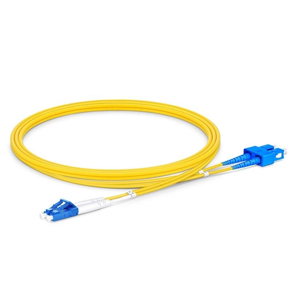
These installation instructions provide overview and specification information for small form-factor pluggable (SFP/ SFP+/SFP28) modules, as well as instructions for installing and removing the modules. SFP (Small Form-factor Pluggable) transceivers are essential components in modern fiber optic networks, enabling network devices such as switches, routers, and servers to transmit and receive data over optical fiber. By converting electrical signals into optical signals—and vice versa—SFP. Gigabit single-mode fiber optic module Common parameters of optical modules 1. Center wavelength 1) 850nm (MM, multi-mode, low cost, but short transmission distance, usually only 500M); 2) 1310nm (SM, single mode, large loss during transmission, small dispersion, generally used for transmission. As a leading provider of fiber optic solutions, Weunion offers a wide range of SFP-compatible products, including optical transceivers, DAC/AOC cables, LC patch cords, and MPO/MTP assemblies. While they may appear to be simple plug-in transceivers, SFP modules are precision-engineered devices that directly influence network. o In optical modules, "core" refers to the light-transmitting channel in the fiber. A 1-core module uses a single fiber core for data transmission, while a 2-core module uses two cores. o Think of a highway. A 1-core fiber is like a single-lane road—only one car (or data signal) can travel at a.
[PDF]
A fiber media converter takes an Ethernet signal on copper (RJ-45) and converts it to an optical signal on fiber, or vice versa. There are also fiber-to-fiber versions that translate between different fiber types, wavelengths, or distances. Full range of Fiber Optic Modems to convert Serial Data, T1, E1, T3, E3 and Phones for fiber communication. Featuring high and low speeds and field-changeable interfaces. Applications include satellite downlinks, DSUs, various Crypto devices, Channel Banks, SCADA and Process Control Networks. In this article, we'll explore the seamless transition from T1 and E1 lines to fiber optics, enabling you to enjoy lightning-fast connectivity. E1 and T1 leased lines are digital technologies that connect two locations with a private, dedicated connection. They offer dependable and secure data. A fiber optic network is a way to transmit data and realize communications via fiber optic cabling instead of Ethernet cabling. A fiber optic network, in other words, utilizes another media to conduct data transmission between the main and edge network devices. Copper Ethernet Cabling VS. These devices are essential when you need to bridge fiber optic cables with Ethernet cables, especially in long-distance or high-speed network setups. There are no specific requirements for this document. The information in this document is based on all Catalyst 9000 Series switches. This includes Doppler.
[PDF]


