
Explore verified suppliers offering low-price fiber optic splice boxes, ideal for wholesale. With options from 24 to 144 cores, start your purchase from 1 unit at an average price around $17. TAKFLY COMMUNICATIONS CO. com! Source over 176 fiber-optic splice closures for sale from manufacturers with factory direct prices, high quality & fast shipping. We support our B2B partners with OEM branding, custom configurations, and bulk order discounts, delivering factory-tested solutions for large-scale. COYOTE Closure, 288f/576f ribbon max, Buffer Tube: 8. 5″ x 22″, Includes (1) 3 Section End Plate, (1) Blank End Plate, Organizer, and Lock Tape sealant. FOSC 600 D Dome Closure, 648ct Single/1728ct Ribbon, 8 Ports, Loaded Without Trays, 4 Ground Lugs, 32. 79″, Price Per Ea. ZIP code to view pricing. ZIP code to. Budco is a stocking distribution company for broadband tools, fiber optic tools and cable tools. Since 1970, Budco has provide cable construction tools, cable installation tools, and cable identification tools including fiber optic test equipment and tools for the telecommunications industry. We. This fiber optic splice box is an outdoor fiber optic splice closure used to protect the twisting and joining (splicing) of fiber optic cables. These splice boxes are not made for in-house, off-the-shelf cabling solutions. Instead, they are for installation by professionals laying new fiber optic.
[PDF]
This splice case protect fiber optic cables and juction from outside plant environment damage. They are made of reinforced ABS or PC plastic, which has high strength and corrosion resistance. In addition, the splice enclosures are all hermetically sealing structure, waterproof and. Standard polycarbonate (PC) or Glassfibre reinforced (PC+GLAS) PP ABS (Acrylnitrile-butadiene -styrene) Slightly lower UV resistance compared with PC. Recommended for outdoor use if protected against weather influences GRP – GLASS FIBRE REINFORCED POLYESTER Polycarbonate and ABS enclosure materials. The fiber optic splice closure is a closed structure used for splicing, protecting and managing optical fibers. Its material selection is crucial to ensure the quality and service life of the fiber optic splice closure. These boxes are well suited as optical cable splice collection points for DAS (Distributed Antenna Systems), MTU (Multi-Tenant Unit) commercial business applications, and MDU (Multi-Dwelling Unit). It is a reentry box which is made of PC or PP material. The shells and the base are sealed with silicone gum. This product can be re-entered and used again after it is opened. Typically selected for high-density OSP splicing and branching. What is the basic structure of Fiber Optic Splice Closure? The basic structure of Fiber Optic Splice Closure includes the box body, box components, sealing ring, and lock buckle.
[PDF]

In this step-by-step tutorial, learn how to splice fiber optic cables like a pro — perfect for telecom technicians, network engineers, and field techs. more 🔧 Watch a real-time fiber optic splicing demo in action!. Fiber cable splicing is a critical step in building reliable fiber optic networks. Whether in data centers, telecom rooms, or outdoor FTTx deployments, proper splicing inside a fiber enclosure ensures low signal loss, long-term stability, and easy maintenance. This guide explains what fiber cable. In this guide, we cover the basics of fiber optic splicing, how to perform splicing using two different methods, and finally some best practices to perform good fiber splicing. What is Fiber Optic Splicing and Why is it Needed? – #1. Whether repairing a broken cable or extending a fiber run, fiber optic splicing ensures light signals travel. Regardless of your level of experience, creating high-quality, high-performance fiber optic networks requires developing your skills in fusion splicing. This guide reveals the secrets to fusion splicing with little fluff—just proven, straightforward techniques refined from years of work in the.
[PDF]

Learn how to splice fiber optic cable using fusion splicing with this complete step-by-step guide. Includes tools, best practices, loss standards (ITU-T G. 652), cost analysis, and FAQs for network engineers and installers. Splicing fiber optic cable is an extremely important phase for making dependable, high-speed communication infrastructures. Regardless of the type of fiber network you're deploying, be it for telecom, enterprise data centers, or smart city infrastructure, fusion splicing provides the benefits of. This is where fiber optic cable splicing—the process of creating a permanent, high-performance join between two fiber ends—becomes critical. For network managers and technicians, a poor splice can lead to significant signal degradation, network downtime, and costly troubleshooting. At Turn-Key. Think of a fiber optic cable splice as the seamless stitching that keeps data flowing through the delicate threads of a network—like a master tailor joining fabric with precision. What is Fiber Optic Splicing and Why is it Needed? – #1. Discover how to efficiently use sleeves and the heat. The answer lies in splicing, both fusion and mechanical. In this comprehensive guide, we will delve into when.
[PDF]
Different networks have different needs when it comes to fiber optic joint closures. At Multilink, we have a variety of closures to meet these needs, including inline types and drop terminals. In our selection, you can find the following termination. Different networks have different needs when it comes to fiber optic joint closures. At Multilink, we have a variety of closures to meet these needs, including inline types and drop terminals. In our selection, you can find the following termination enclosures and splice boxes for use with different cable sizes and numbers of drops: Optima™: The Op. The securing, storing and supporting of fiber optics and splices makes up an important step of fiber optic deployments in the field. Whether connecting to aerial or underground cables, telecommunications companies rely on fiber optic closures to protect and facilitate fiber splices and regular maintenance in Fiber to the Home (FFTH) and other indoo. With more than 35 years of experience, Multilink is a leader in the telecommunications industry. We make innovative products and help our customers succeed by providing high-quality equipment that's laboratory tested and proven to perform. Telecommunications companies often have unique requirements for their equipment. If you have a specific fiber.
[PDF]

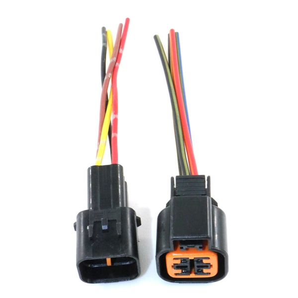
Just count the number wire leads coming from the connector and scroll to the section with that number. Executive Summary: A fiber optic pigtail is one of the most commonly specified yet least understood components in structured cabling. Get the wrong connector type, the wrong polish, or skip proper fusion splicing technique—and you're looking at elevated signal loss, increased back reflection, and a. Terminal Release Tools RTTP #s: NUD900-001, NUD900-002, NUD900-003 and NUD105-R025E Flex Probe Kit are available through RTTP. 2ND GENERATION - EXPANDED TO INCLUDE 8 AWG APPLICATIONS! Ford has identified through testing and engineering analysis, the optimal repair procedure for solderless wire. It includes an identification guide with images of various connectors and kits, highlighting their use in vehicle electrical repairs. The document details specific toolkits such as the Ford Flex Probe Kit and the Wire Splice Tool Kit, designed for repairing electrical wiring harnesses. Match the connector in the picture. They contain 5 uninsulated butt splices, 5 pieces of dual wall adhesive-lined heat shrinkable tubing, and the new instruction sheet detailing the approved wire splice procedure as defined by Ford Motor Company. Expanded wire gauge applications for these splices can be found in Technical Service.
[PDF]

In this guide, we'll walk you through the entire process of preparing fiber optic cable for splicing and termination to fiber connectors. We'll explore the necessary tools, safety precautions, and step-by-step procedures for cable connectors, mechanical and fusion. At the heart of any robust fiber optic network lies a crucial process: Preparing a fiber cable for termination of a connector or splice. Two types of splices are used in fiber optic cabling one is Mechanical the other is Fusion. Whether you're installing a new network, expanding an existing one, or. Splicing fiber optic cable is an extremely important phase for making dependable, high-speed communication infrastructures. Regardless of the type of fiber network you're deploying, be it for telecom, enterprise data centers, or smart city infrastructure, fusion splicing provides the benefits of. Think of a fiber optic cable splice as the seamless stitching that keeps data flowing through the delicate threads of a network—like a master tailor joining fabric with precision. This article explains when. We terminate fiber optic cable two ways - with connectors that can mate two fibers to create a temporary joint and/or connect the fiber to a piece of network gear or with splices which create a permanent joint between the two fibers. These terminations must be of the right style, installed in a. So in essence, fiber optic splicing is a process used to join two separate fiber optic cables together.
[PDF]

The most common fiber splice closure sealing methods include heat-shrink, mechanical, and gel-based sealing. While they all share the goal of isolating external factors, they achieve this in different ways. Gel seals utilize a soft gel material that adheres tightly to the cable. Another type of closure is a hybrid of splices and a patch panel. These are often used with fiber to the home (FTTH) networks where drop cables to individual subscribers are factory made preterminated cables and just require plugging in connectors - no splicing required. Here is two examples of. Fiber optic closures protect and organize cable splices, ensuring long-term stability in both outdoor and indoor networks. This guide explains their functions, types, and selection criteria, while showing how FiberMania's OEM customization helps achieve higher reliability and efficiency in modern. In modern FTTx and PON networks, fiber optic splice closures are the enclosures that protect fiber splice points from moisture, dust, and physical stress. Installing a fiber optic splice closure efficiently and effectively requires attention to detail and. 1 Sealing of the fiber optic splice closure (1) Clean the sealing groove around the joint box with alcohol cotton/wipes. (2) Insert the sealing strip into the sealing groove of the lower half of the joint box. This guide is written to provide a complete and engineering-oriented understanding of fiber optic splice closures—from basic concepts and.
[PDF]

Mainly 9steps: Step 1: cut cable with cutting machines in lengths Step 2: put the connector spare parts on the cable Step 3: Strip cable jacket, coating till bare fiber, and make all parts in ready Step 4: Insert fiber into ferrule, glue dispenser and heat oven Step 5:. Mainly 9steps: Step 1: cut cable with cutting machines in lengths Step 2: put the connector spare parts on the cable Step 3: Strip cable jacket, coating till bare fiber, and make all parts in ready Step 4: Insert fiber into ferrule, glue dispenser and heat oven Step 5:. Learn how to make a fiber optic patch cord step by step, from preparation to testing, for reliable high-performance connections. Most guides on making fiber optic patch cord 1 s feel incomplete. They often focus on the final assembly steps, leaving the foundational stages a mystery. From cable cutting to connector assembly and testing, you will gain valuable insights into the production of. Fiber optic patch cords and Pigtails are very important passive fiber optic components in fiber optic networks. Use the fiber optic cleaver to cut the. This document describes the installation and use of the mode-conditioning patch cords listed in Table 1. A mode-conditioning patch cord is shown in Figure 1 IEEE 802. 3z-compliant optical fiber assembly consisting of a single-mode fiber permanently coupled off-center to a 62. 5-micron multimode.
[PDF]

Single-mode optical splitters are optimized for single-mode optical fiber, while multimode optical splitters are tailored for use with multimode optical fiber. An Optical Splitter, also known as a beam splitter, is a passive optical device that divides a single input optical signal into two or more output signals. Conversely, it can also combine multiple signals into one. Its primary role is in Passive Optical Networks (PON), which are the foundation of. This guide demystifies fiber optic splitters, explaining their design, operating principles, types, key specifications, and real-world applications. It can distribute the optical energy transmitted through a single fiber to two or more fibers in a predetermined ratio or combine the optical energy from multiple fibers into one fiber. “Passive” means it needs no. You use optical couplers and splitters to split or join signals in fiber networks. For example, optical splitters send light to many output ports. This lets you connect more users to one network terminal. There are different types of fiber optic splitters available, with two of the most common being Fused Biconical Tapered (FBT) splitters and Planar Lightwave.
[PDF]

Check for proper IP/NEMA ratings and material quality. Ensure safe placement: install in dry, accessible areas with good ventilation and at appropriate height (typically ~1. Practice good wiring: secure grounding, neat cable management, proper insulation, and correct wire gauge and. In this guide, we'll break down everything you need to know to install a distribution box correctly and confidently. Choose the right box based on environment (indoor/outdoor), load capacity, and durability. It is usually equipped with circuit breakers, fuses, terminal connectors, and other components. It is mainly used to isolate fault circuits, prevent overload, and ensure the safe operation of. Think of your home's distribution box as the Grand Central Station of your electrical system. Just like travelers need clear pathways and safety protocols, your electrical circuits need proper management to prevent chaos. The National Electrical Code (NEC) requirements might seem like bureaucratic. The ideal location to install electrical distribution boxes should keep a distance from water, flammable and explosive substances and corrosive substances. If they need to be placed outdoors, especially in high humidity, you must ensure their waterproofness. And all the switching and protective devices are installed in the distribution box. Single Phase Distribution Box generally consists of Double Pole MCBs, Single Pole MCBs, and RCCBs.
[PDF]

Poland's high voltage oil insulated switchgear market is estimated at USD 145–175 million in 2026, with a compound annual growth rate of 3. 5% through 2035, driven primarily by grid modernization and renewable energy integration. Successful go‑live of day-ahead and intraday capacit. informs that under the Single Day-Ahead Marke. Due to changes in information requirements for the electricity market and Polish Power System Operation a new website containing system data has been launched. Transmission substations account for approximately 55–60% of. The electricity transmission network in Poland is managed by Polskie Sieci Elektroenergetyczne SA (PSE), which is the sole transmission system operator (TSO) in the country. The entire power system in Poland and throughout Europe (excluding the frequency of railway electric traction in Germany and. The ANIA Electrical Centre, operating within the structure of ANIA HOLDING, has been providing comprehensive solutions for the distribution of electrical goods for over 30 years. PSE is the owner of Poland's high voltage electricity grid and is responsible for grid. Polenergia Dystrybucja builds and maintains its own power infrastructure across Poland, through which it distributes and sells electricity. Your browser does not support the video tag. Our clients include shopping malls, office buildings, industrial parks, warehouse centers, housing cooperatives.
[PDF]

The following are the precautions for the use of Gigabit optical transceivers and 10 Gigabit optical transceivers, some common fault causes, and corresponding troubleshooting methods and solutions. Avoid damage. In the formation of modern networks, optical modules are essential equipment, of which Gigabit optical modules and 10 Gigabit optical modules are popular because of their high speed and stable transmission rate and wide applicability. However, the failure of optical modules is a common problem. 10G SFP+ optical modules remain one of the most widely deployed transceiver solutions in data centers, telecom networks, enterprise switching, and cloud-scale architectures. Their compact size, low power consumption, and versatility across multimode and single-mode fiber make them a critical. Gigabit optical transceivers and 10 Gigabit optical transceivers are an essential part of modern network communication, but they will inevitably encounter some failures during use. This article dives into technical specifications, real-world usage scenarios, selection criteria, and. Single-fiber bidirectional (BIDI) optical modules must be used in pairs. For example, SFP-10G-BXD1 must be used with SFP-10G-BXU1. Cisco XFP Module Main features of the Cisco XFP Module include:.
[PDF]