One of the most common ways to test fiber optic cables is with a light source, which emits light through the cable to detect any potential problems. LED light sources emit. Fiber optic cables are a top choice for high-speed communication systems and can also serve as sensors to measure and monitor various quantities. Modern. Document the end-to-end results for the fiber optic segment you just tested. Related: Data Center Cabling Best Practice Guide Using optical time domain reflectometer testing, you'll measure the length of the fiber optic cable, attenuation, and any events occurring on that fiber segment. Events are. A photodiode is a semiconductor diode sensitive to photon radiation, such as visible light, infrared or ultraviolet radiation, X-rays and gamma rays. It produces an electrical current when it absorbs photons. This can be used for detection and measurement applications, or for the generation of. A typical fiber optic communication system consists of three primary components: a transmitter, a fiber optic cable (the transmission medium), and a receiver. The transmitter usually incorporates a Light Emitting Diode (LED) which converts digital binary data into light waves. The studies cover fiber optic components that have standard SMA connectors to couple with SMA-SMA connectorised PMMA (plas otodiode and a phototransistor. It has a built-in optical power meter an the associated power supplies. Apart from LPS04, the accessories.
[PDF]
The VFL 30mW 30km tester meter is a powerful and versatile instrument capable of tracing and identifying fiber optic cable faults within a range of 30 kilometers. It employs a 30mW VFL light source, which is more than sufficient for long-distance fiber optic testing applications. This QuickTreX ® high quality visual fault locator (VFL) laser test pen is compact, rugged, and perfect for locating bends and breaks in jacketed or bare fiber within 30Km. It's also great for identifying specific connectors in patch panels. This VFL emits red light by using a 650nm semiconductor. Easy to Check Fiber Faults - This visual fault locator can accurately detect and locate fiber breaks, poor connections, bending, or cracking. The detector will emit a 650nm bright light for fiber tracing, breaks or faults in the fiber will refract the light. PRACTICAL DESIGN AND EXCELLENT FUNCTION –. The Pen Shape Visual Fault Locator (VFL) is a robust, cost-effective fiber optical cable test tool for locating faults within OTDR dead zones. As a visual fault identifier (VFI), it can quickly identify faults in fiber optic jumper cables, distribution frames, patch panels, and splice trays. Using. New: A brand-new, unused, unopened, undamaged item in its original packaging (where packaging is. Packaging should be the same as what is found in a retail store, unless the item was.
[PDF]

When it comes to testing fiber optic cables, a Visual Fault Locator (VFL) is an essential tool in your toolkit. A VFL is used to detect faults, breaks, or bends in fiber optic cables by emitting a bright red light that is visible even through the fiber's jacket. Let's dive into everything you need to know about mastering VFLs. It's a cost-effective and. Visual Fault Locator (VFL) testing is one of the most fundamental inspection methods used in FTTH, ODN, and data center environments. A VFL emits a visible red laser (typically 650 nm) that travels along the fiber core and leaks out at points of excessive loss, fiber breaks, or microbends. Although. The Fiber Visual Fault Locator Kit is an essential tool for network technicians and engineers; it provides an accurate and quick method of finding such problems as breaks, bends or faults that may affect the network's operation. It works by injecting a visible red laser light (usually in the 650nm wavelength) into the fiber. When the light encounters a fault, such as a break, bend, or bad splice, it leaks out of the fiber, making the. Conducting efficient, repeatable fiber optic cable certification requires an array of specialized test equipment: Optical Loss Test Set (OLTS) – Integrates adjustable light source and power meter for efficient, Tier-1 insertion loss testing. Visual Fault Locators – Handheld devices projecting.
[PDF]

In Q1 2019 NSS Labs performed an independent test of the Oracle Talari SD-WAN E1000 v7. NSS has created three use cases to represent the most common reasons why enterprises deploy software-defined wide area network (SD-WAN) products: Manageability & Cost, Performance, and Security. The troubleshooting tools are now easily accessible from the various monitoring pages of Cisco SD-WAN Manager, such as Site Topology, Devices, Tunnels, and Applications, thereby providing you with context-based troubleshooting guidance. For information on interface bandwidth, see the Interface Summary Report. This report is available in WatchGuard Cloud for Fireboxes that run Fireware v12. To view the report, you must configure. The Monitoring tab is a dashboard that displays a summary widgets of all your SD-WAN device health metrics. This tool provides actionable intelligence about the activity on your SD-WAN network, by allowing you to quickly identify applications or links experiencing performance issues. The ideal. Certifications, manuals, datasheets, and specifications for hundreds of thousands of electronic devices. Jump directly to brand. be attenuated by at least 30 dB relative to the maximum in-band peak PSD level in 100 kHz. Set the RBW = 100 kHz, VBW = 300 kHz, Detector = peak. Set Sweep time = auto couple, Trace mode = max hold. Use the peak marker function to determine the maximum amplitude level.
[PDF]

Fiber Bragg grating (FBG) sensors have emerged as advanced tools for monitoring a wide range of physical parameters in various fields, including structural health, aerospace, biochemical, and environmental applications. This review provides a comprehensive overview of FBG sensor technology. A fiber Bragg grating (FBG) is a type of distributed Bragg reflector constructed in a short segment of optical fiber that reflects particular wavelengths of light and transmits all others. This is achieved by creating a periodic variation in the refractive index of the fiber core, which generates a. Abstract: Fiber Bragg Grating (FBG) sensors have emerged as versatile tools for various sensing applications due to their unique properties such as small size, immunity to electromagnetic interference, and high sensitivity. This study provides a comprehensive review of FBG sensor technology and its. Fiber Bragg Gratings (FBGs) are considered excellent sensor elements, suitable for measuring various engineering parameters such as temperature, strain, pressure, tilt, displacement, acceleration, load, as well as the presence of various industrial, biomedical and chemical substances in both static. This SPIE Tutorial Text excerpt discusses the usefulness and versatlity of fiber Bragg gratings. Werneck, Regina Célia da Silva Barros Allil, and Fábio Vieira Batista de Nazaré 10 November 2017 Publications The development of optical fibers has revolutionized not only.
[PDF]
This comprehensive handbook will offer a completely updated and revised guide to lasers and laser systems, including the full range of their technical applications. Laser diodes offer high power for their size and produce electrical-power-efficient laser radiation. They consist of a p-n semiconductor junction, with a forward bias voltage applied to trigger a current through the junction. This induces population inversion (of electrons in the excited state) in. A diode laser, also known as a laser diode or semiconductor laser, is a compact electronic device that converts electrical energy directly into coherent light through the process of stimulated emission. The term “laser” is actually an acronym, standing for Light Amplification by Stimulated Emission of Radiation. The first volume outlines the fundamental components of lasers, their properties and working principles, with brand new chapters in. From telecommunications and data storage to medical surgery and 3D sensing, a laser diode is essential for barcode scanners, printers, and industrial cutting. The laser diode is an unsung hero of modern technology. Operational Mechanism: Laser diodes create light through stimulated emission within an optical cavity, with the light's properties influenced by the semiconductor.
[PDF]

In this article, you will learn the step-by-step process of testing your solar panels using a multimeter. We will cover the essential tools you need, the specific measurements to take, and how to interpret the results. A $15 multimeter and 5 minutes of testing can diagnose most solar panel problems. Measure Voc (open circuit voltage) — if it reads 0V, the panel or wiring is dead. If it reads 60–80 % of rated, a bypass diode has failed. By the end of this guide, you will be equipped with the knowledge to diagnose. Learning how to test solar panel with multimeter is useful for homeowners, technicians, farmers, and anyone using solar energy systems. A digital multimeter allows you to check voltage, current, continuity, and resistance. Fluke recommends using the Fluke 117 Electrician's Multimeter or Fluke 283 FC CAT III 1500 V Digital Multimeter to test solar modules. Here's how a technician tests solar modules with a multimeter:. A multimeter is an indispensable tool for anyone working with solar panels, allowing for accurate measurements and diagnostics. It empowers users to assess the performance, identify faults, and ensure optimal energy production. Perfect for DIY solar builders, RV owners, o. more Audio tracks for some languages.
[PDF]
This study presents the experimental investigations on heat transfer and airflow in a closed refrigerated display cabinet. Air and product temperatures and air velocity were measured with thermocouples and.
[PDF]

Recommendation ITU-T L. 101 describes characteristics, construction and test methods of optical fibre cables for buried application. 0, in February 2016. The short answer, based on general industry standards and the National Electrical Code (NEC), is that fiber optic cable is typically buried between 24 inches (60 cm) and 30 inches (76 cm) deep. However, simply hitting this depth isn't enough to guarantee your network survives. Factors like the. Underground fiber optic cable installation follows specific standards that govern burial depth, testing methods, installation techniques, and safety requirements. 5 is an article in the National Electrical Code that addresses requirements for underground electrical installations, including minimum cover requirements—the measurement used to determine the distance from the top of an underground cable or raceway to the finished grade. 5. Estimate minimum burial depth (cover) for underground electrical, fiber, and low-voltage cable runs using a practical, code-aware ruleset. Use this page to plan trench depth, compare conduit options, and prepare for inspection conversations. Use this calculator to estimate a minimum burial depth. Recommendation ITU-T L. This depth is generally considered the absolute shallowest for any telecommunications cable that is not placed.
[PDF]
3‑E “Optical Fiber Cabling and Components Standard” was developed by the TIA TR‑42. 11 Optical Fiber Systems Subcommittee and published in September, 2022. Fiber optic patch cables are ideal for supporting high speed telecommunication network fiber applications. They are manufactured and tested in compliance with TIA 604 (FOCIS), IEC 61754 and YD/T industry standards. OM1, OM2, OM3, OM4, OM5 or OS2 fiber types are available to meet the demand of. Leviton fiber optic patch cords meet or exceed industry standards to make sure you get the performance you expect. They are available in multimode (OM1, OM3, OM4, OM5) and single-mode (OS2) fiber types, with a range of SC, ST and LC connectors. These standards are very important. They make sure patch cords work well, are safe, and can connect with other equipment. The high-quality fiber optic. ANSI/TIA‑568.
[PDF]

Have all of our in-stock product information and specifications right at your fingertips in digital PDF format. is a world class manufacturer of electronic wire and cable, both copper and fiber optic cable. Because of NATIONAL's service attributes and extensive cable manufacturing abilities, we offer a unique set of brand attributes: personalized service and product selection. You can get just about any. DOWNLOAD the Complete Catalog (PDF format 3. 9 MB) Download part numbers, descriptions and specifications of National Wire in-stock products by specific category or download the entire catalog. Heavy-Duty Flexible PVC Insulation – Crack-resistant and built for long-term durability. Versatile Use – Perfect for automotive, solar wiring, LED lighting, home projects, and RV systems. Guaranteed for. Fill out the form with your project details, and we'll help you every step of the way. Feedback! Don't miss out on anything, subscribe to our Newsletter! NNC © Copyright 2009 - 2026. Forgot your password?. Important! LANshack offers premium fiber optic cable & copper wire assemblies. We have all the components to optimize & install your network!. welcome to taobao purchase national standard soft copper wire 25 square millimeters 16 square millimeters copper core cable high-volume building welding machine welding wire welding machine welding machine welding soft copper wire.
[PDF]
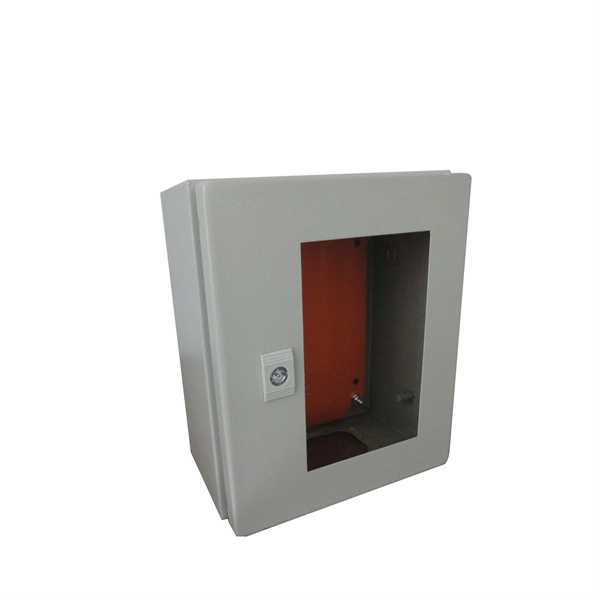
What does it take to make an effective explosion-proof junction box or cabinet? An incredible mechanical engineering design is what you need. Design for such enclosures and storage boxes differ with each m.
[PDF]
Time domain reflectometers are commonly used for in-place testing of very long cable runs, where it is impractical to dig up or remove what may be a kilometers-long cable. They are indispensable for preventive maintenance of telecommunication lines, as TDRs can detect resistance on joints and connectors as they corrode, and increasing insulation leakage as it degrades and absorbs. OverviewA time-domain reflectometer (TDR) is an electronic instrument used to determine the characteristics of by observing. It can be used to characterize and locate faults in metallic cables (for. A TDR measures reflections along a conductor. In order to measure those reflections, the TDR will transmit an incident signal onto the conductor and listen for its. If the conductor is of a uniform.
[PDF]